Low thermal stress catadioptric imaging optics

a catadioptric and low thermal stress technology, applied in the field of optical imaging systems, can solve the problems of difficult to achieve the effect of delivering contrast, contrast uniformity, color uniformity for the projected image, and difficult to achieve the effect of reducing birefringence susceptibility, improving image quality, and improving image quality

Active Publication Date: 2013-05-02
IMAX THEATERS INT
View PDF6 Cites 20 Cited by
  • Summary
  • Abstract
  • Description
  • Claims
  • Application Information

AI Technical Summary

Benefits of technology

[0034]It has the advantage that the performance of the imaging optics when they are used to produce images using polarized light will not be significantly affected by thermal changes resulting from the absorption of the imaging light.
[0035]It has the further advantage that the imaging optics can be used for stereoscopic projection systems without producing objectionable cross-talk between the left- and right-eye images due to stress-birefringence-induced depolarization.
[0036]It has the additional advantage that the reduced birefringence susceptibility is achieved while simultaneously achieving an acceptable image quality level.

Problems solved by technology

Alternately, liquid crystal devices (LCDs), which modulate light by altering polarization states of transiting light, can be used instead of DLP devices, with comparative benefits of higher resolution and larger device size, but greater difficulty in delivering contrast, contrast uniformity, and color uniformity for the projected image.
Color space separation avoids problems in handling polarized light from the projector, at the screen, and with the viewer's glasses, but light inefficiencies and the cost of the glasses are problematic.
Although this arrangement offers efficient use of light, it can be an expensive configuration.
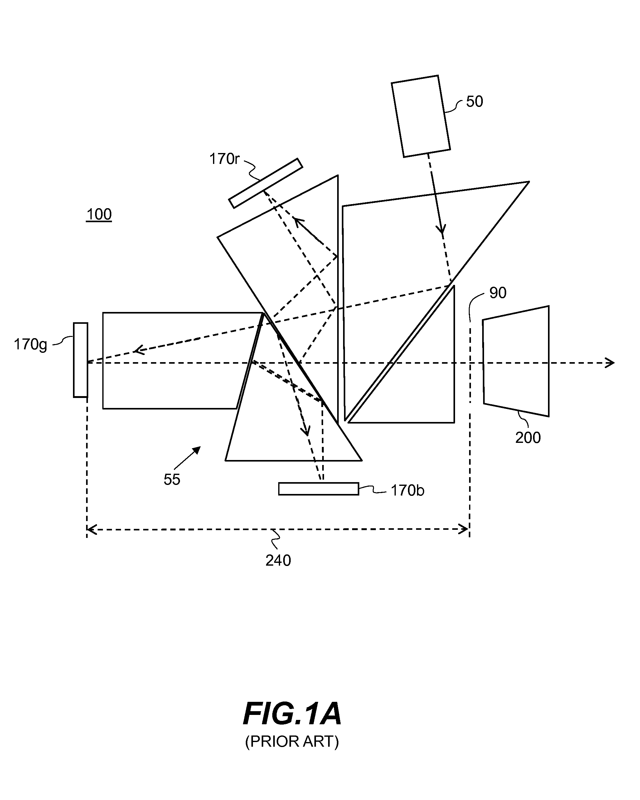
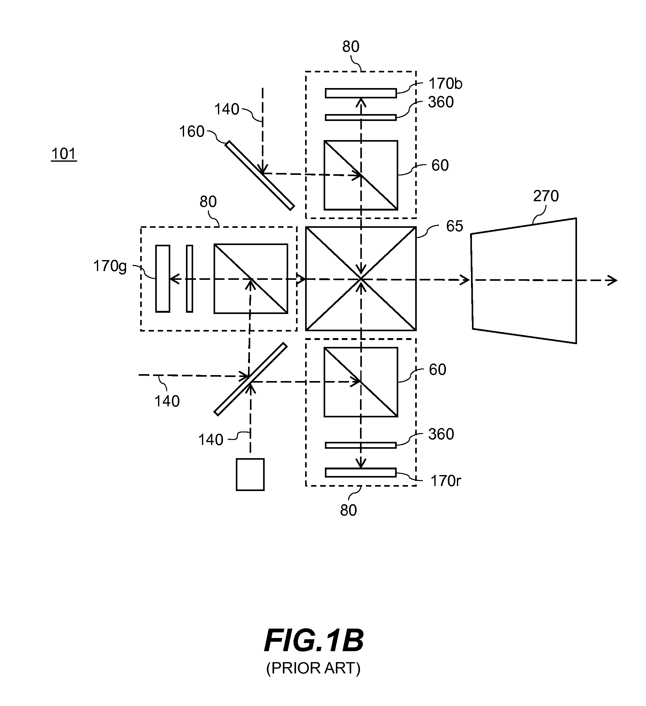
This output is unpolarized because unpolarized light sources (lamps) are used, and the typical DLP device windows are depolarizing (due to stress induced birefringence).
This can cause viewers to experience ghost images, for example such that the left eye not only sees a bright left-eye image but a dim right-eye image.
However, to date, the desire for laser-based projection systems has been unfulfilled, in part as compact, robust, low-to-moderate cost, visible wavelength laser technologies had not emerged in a commercializable form, particularly for green and blue.
Presently, these power levels can only be accomplished by optically combining the output of multiple laser arrays in each color channel.
Of course, each approach has its advantages and disadvantages, relative to trade-offs of simplicity, cost, and susceptibility to laser failure.
However, this simplistic view is unrealistic for high power laser-based projection applications such as for digital cinema.
Of course, these high light levels can bring accompanying thermal issues, as illumination light, imaging light, or even stray light encounters internal surfaces or materials.
There are already numerous problems caused by the intense light in conventional lamp based systems, some of which will only be amplified in laser-based systems.
That in turn can change the polarization orientations of the transiting light, thereby impacting image contrast, image contrast uniformity, color uniformity or other attributes that reduce the perceived on-screen image quality.
In the case of spatial light modulator devices, and liquid crystal on silicon (LCOS) devices in particular, a problem can occur where the intense light causes thermal loading and stress birefringence in the counter electrode substrate, which is internal to the device itself.
However, under high light intensities, the portion of the light transiting the counter electrode substrate that is absorbed can cause sufficient internal heating to induce stress birefringence, which in turn alters polarization orientations.
As alluded to earlier, a similar problem presently exists with the cover glass windows for DLP modulators; but as these devices have generally not been used to modulate intense polarized light with an expectation of maintaining polarization states, neither the glass selection nor the glass mounting design were undertaken with the goal of minimizing stress birefringence.
In contrast, in U.S. Pat. No. 7,357,511 to Aastuen et al., the inventors suggest that the glasses proposed by Cline et al., for satisfactory low stress birefringence (such as Schott SK5 or Schott BK7) are actually inadequate, and that contrast degradation from these alternate glasses is actually too large.
It is also noted that unwanted birefringence has caused image quality problems in fields outside of the projection space, including in the area of micro-lithography.
In extreme cases, optical self-focusing effects in non-linear optical materials can cause optical damage or breakdown.
However, the added complexity of further controlling thermally-induced stress birefringence, relative to the design of an imaging lens system and the constituent lens elements, is a problem that is neither taught nor anticipated in the prior art.

Method used


Image

  • Low thermal stress catadioptric imaging optics
  • Low thermal stress catadioptric imaging optics
  • Low thermal stress catadioptric imaging optics

Examples


Embodiment Construction

[0078]The present description is directed in particular to elements forming part of, or cooperating more directly with, apparatus in accordance with the invention. It is to be understood that elements not specifically shown or described may take various forms well known to those skilled in the art.

[0079]The invention is inclusive of combinations of the embodiments described herein. References to “a particular embodiment” and the like refer to features that are present in at least one embodiment of the invention. Separate references to “an embodiment” or “particular embodiments” or the like do not necessarily refer to the same embodiment or embodiments; however, such embodiments are not mutually exclusive, unless so indicated or as are readily apparent to one of skill in the art. The use of singular or plural in referring to the “method” or “methods” and the like is not limiting. It should be noted that, unless otherwise explicitly noted or required by context, the word “or” is used ...


PUM


Abstract

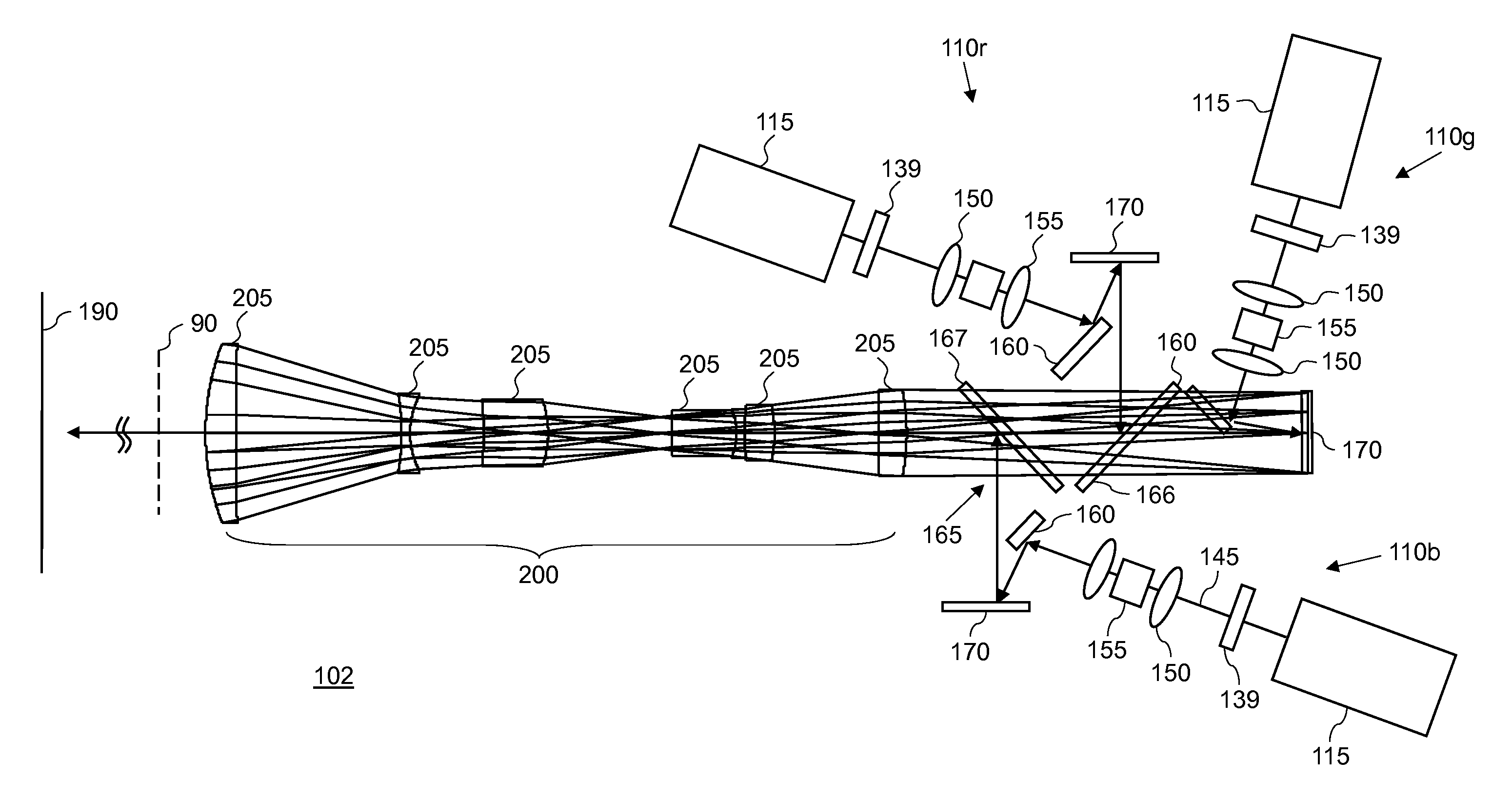
Imaging optics having reduced susceptibility to thermally-induced stress birefringence for imaging an object plane to an image plane; comprising an aperture stop positioned between the object plane and the image plane; a first group of optical elements located on the object plane side of the aperture stop; and a second group of optical elements located on the image plane side of the aperture stop. The optical elements in the first and second groups that are immediately adjacent to the aperture stop are refractive lens elements fabricated using optical materials having a negligible susceptibility to thermal stress birefringence, and the other optical elements are a combination of reflective optical elements and refractive lens elements fabricated using optical materials having at most a moderate susceptibility to thermal stress birefringence.

Description

CROSS-REFERENCE TO RELATED APPLICATIONS[0001]Reference is made to commonly assigned, co-pending U.S. patent application Ser. No. 12 / 784,520 (96201), entitled “Low thermal stress birefringence imaging lens”, by Kurtz et al.; to commonly assigned, co-pending U.S. patent application Ser. No. 12 / 784,521 (96314), entitled “Designing lenses using stress birefringence performance criterion”, by Bietry et al.; to commonly assigned, co-pending U.S. patent application Ser. No. 12 / 784,523 (96315), entitled “Low thermal stress birefringence imaging system”, by Kurtz et al.; and to commonly assigned, co-pending U.S. patent application Ser. No. ______ (Docket K000091), entitled “Low thermal stress catadioptric imaging system”, by Silverstein et al., each of which is incorporated herein by reference.FIELD OF THE INVENTION[0002]The present invention relates to optical imaging systems, and more particularly to imaging lens having a low sensitivity to stress birefringence induced by the thermal load ...

Claims


Application Information

Patent Timeline
Patent Type & Authority Applications(United States)
IPC IPC(8): G02B17/08
CPCG02B1/00G02B7/008G02B5/3083G02B27/149G02B27/283G02B27/48H04N9/3144H04N9/3105H04N9/3152G03B21/2013G03B21/2066G03B21/2073G03B21/208G03B33/12G02B23/06
Inventor KURTZ, ANDREW F.BIETRY, JOSEPH RAYMOND
Owner IMAX THEATERS INT
Why Eureka
Try Eureka