Cryogenic balloon device with radiofrequency tip

Active Publication Date: 2013-05-02
MEDTRONIC CRYOCATH LP
View PDF4 Cites 21 Cited by
  • Summary
  • Abstract
  • Description
  • Claims
  • Application Information

AI Technical Summary

Problems solved by technology

Exchanging these various catheters during a procedure can cause inaccuracies or movement in the placement and location of the distal tip with respect to the tissue to be ablated, and may further add to the time required to perform the desired treatment.
These potential inaccuracies and extended duration of the particular procedure increase the risk to the

Method used


Image

  • Cryogenic balloon device with radiofrequency tip
  • Cryogenic balloon device with radiofrequency tip
  • Cryogenic balloon device with radiofrequency tip

Examples


Embodiment Construction

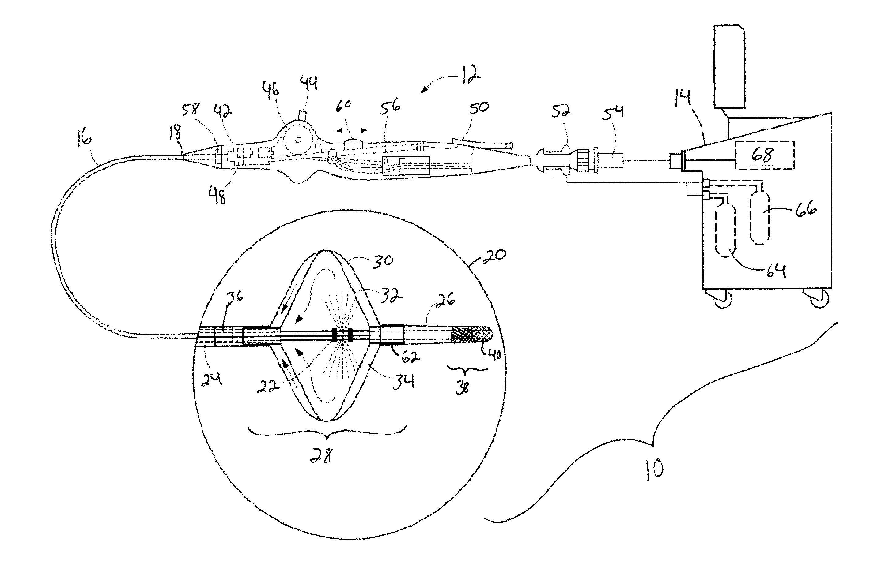
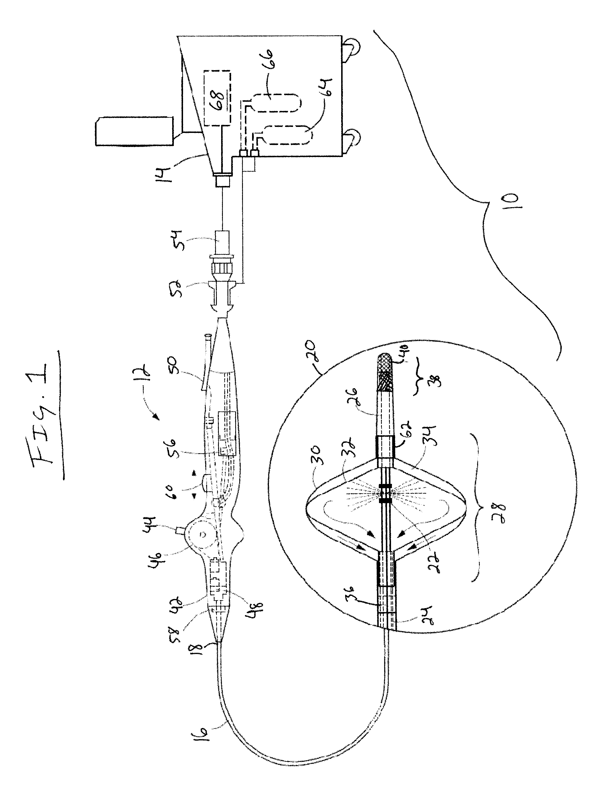
[0012]The present invention advantageously provides a medical system having the ability to provide ablative patterns of various shapes to treat one or more targeted tissue sites. Referring now to the drawing figures in which like reference designations refer to like elements, an example of a medical system constructed in accordance with principles of the present invention is shown in FIG. 1 and generally designated as “10.” The system 10 generally includes a medical device 12 that may be coupled to a control unit 14. The medical device 12 may include a medical probe, a catheter, or other instrument, and may generally include one or more treatment regions for energetic or other therapeutic interaction between the medical device 12 and a treatment site. The treatment region(s) may deliver, for example, cryogenic therapy, radiofrequency energy, electroporation energy or other energetic transfer with a tissue area in proximity to the treatment region(s), including cardiac tissue.

[0013]T...


PUM


Abstract

An intravascular ablation device, including a flexible elongate body; an expandable element positioned on the elongate body; a radiofrequency or electroporation treatment segment located distally of the expandable element; a cryogenic coolant source in fluid communication with an interior of the expandable element; and a radiofrequency or electroporation energy source in communication with the radiofrequency or electroporation treatment segment.

Description

CROSS-REFERENCE TO RELATED APPLICATION[0001]n / aSTATEMENT REGARDING FEDERALLY SPONSORED RESEARCH OR DEVELOPMENT[0002]n / aFIELD OF THE INVENTION[0003]The present invention relates to a method and system for thermal tissue treatment, and in particular, towards systems and methods of use thereof for treating one or more tissue sites having varying geometries with varying treatment modalities.BACKGROUND OF THE INVENTION[0004]Minimally invasive devices, such as catheters, are often employed for surgical procedure, including those involving ablation, dilation, and the like. In a particular situation, an ablation procedure may involve creating a series of inter-connecting lesions in order to electrically isolate tissue believed to be the source of an arrhythmia. During the course of such a procedure, a physician may employ several different catheters having variations in the geometry and / or dimensions of the ablative element in order to produce the desired ablation pattern. Each catheter may...

Claims


Application Information

Patent Timeline
IPC IPC(8): A61B18/02A61B18/18
CPCA61B18/1492A61B2018/0022A61B2018/00642A61B2018/00702A61B2018/00714A61B2018/00791A61B2018/00613A61B2018/00898A61B2018/0212A61B2018/0262A61B18/02A61B2018/00357A61B2018/00863A61B2018/00994A61B2018/00255A61B2018/00375A61B2018/00351
Inventor LALONDE, JEAN-PIERRE
Owner MEDTRONIC CRYOCATH LP
Why Eureka
Try Eureka