
Cooling module for modular data center and system comprising the cooling module and at least one server module

a cooling module and data center technology, applied in the field of cooling modules for modular data centers, can solve the problems of data center servers producing a significant amount of heat, requiring large amounts of energy to cool, and the cost of air conditioning a data center can be quite high

Inactive Publication Date: 2013-05-09
COMMSCOPE INC
View PDF13 Cites 46 Cited by
  • Summary
  • Abstract
  • Description
  • Claims
  • Application Information

AI Technical Summary

Benefits of technology

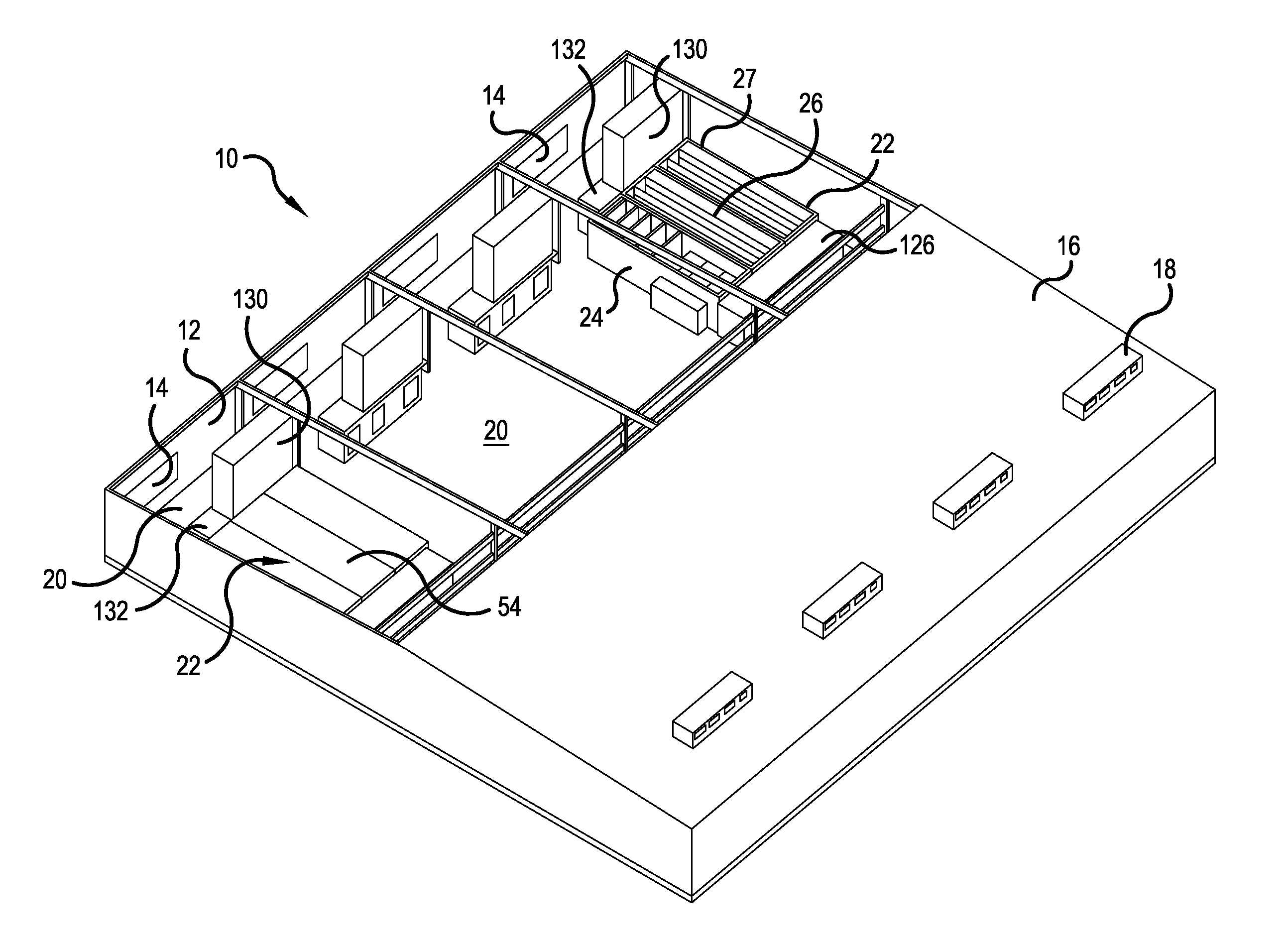
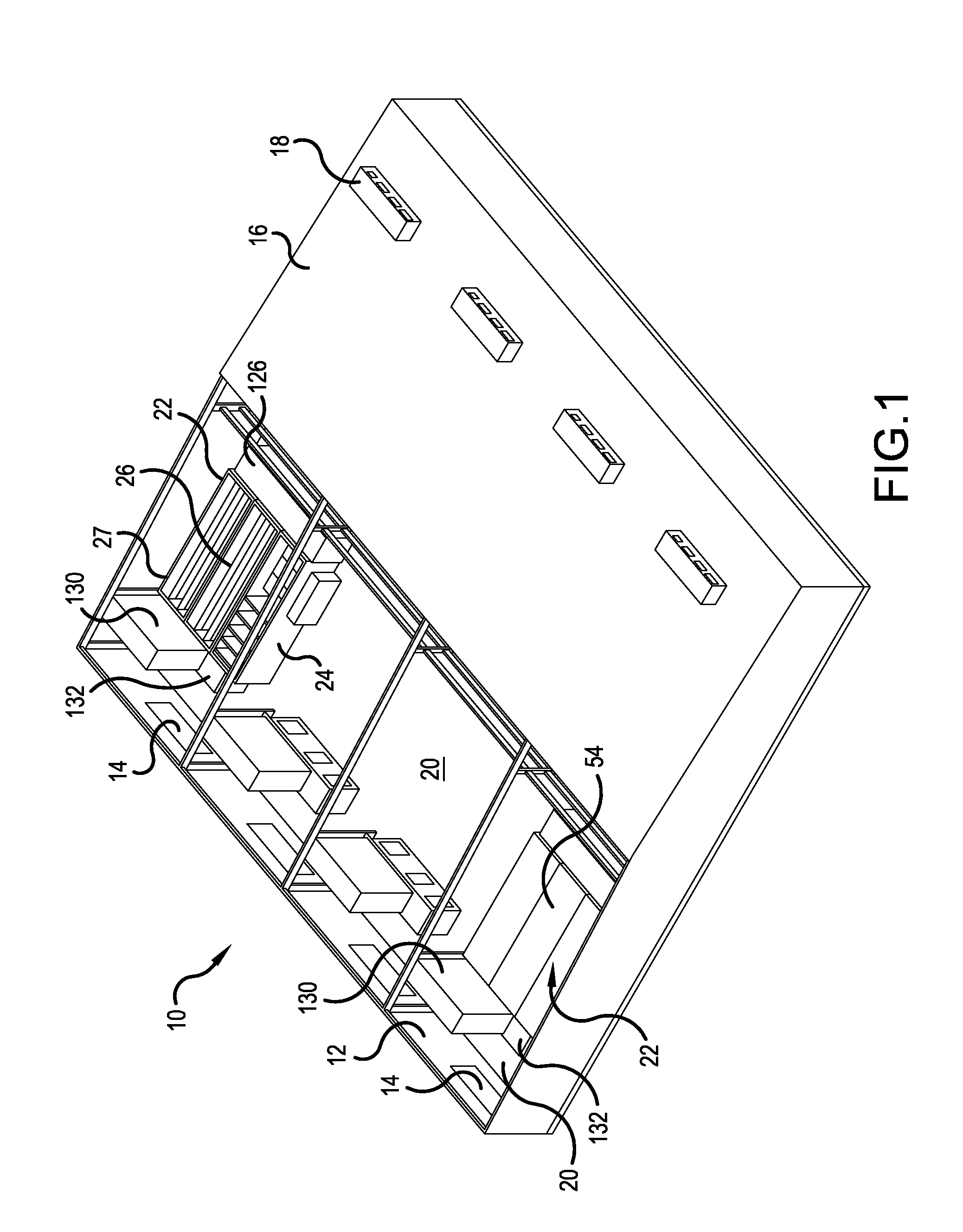
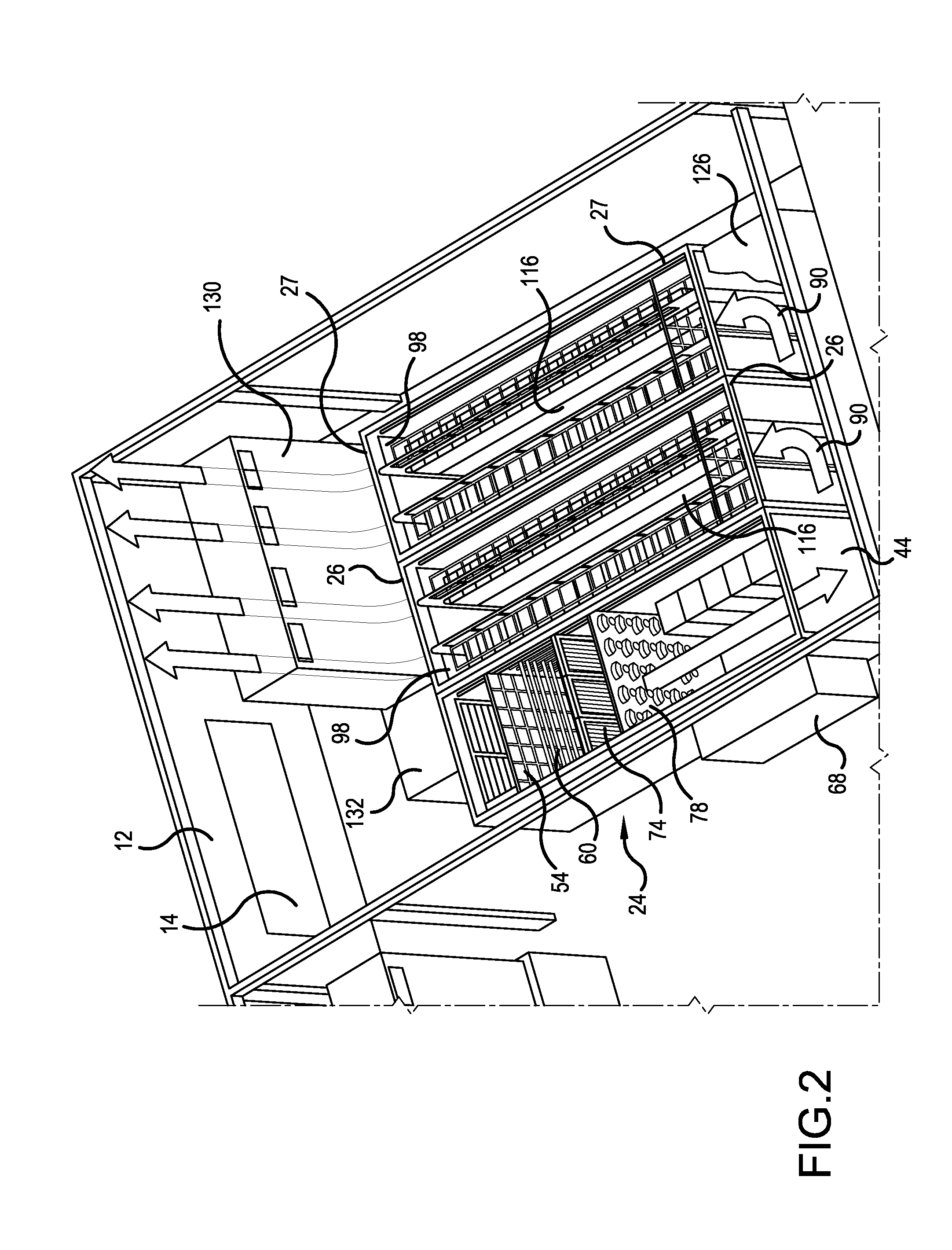
The present invention provides a cooling module for server modules that can efficiently cool multiple servers. The cooling module includes a housing with an interior containing air, an intake, an outlet, and a fan to move air through the module. The cooling module also has a sprayer to spray a mist into the air for evaporative cooling. The cooling module can be connected to the server modules through a plenum, and the system includes sensors and a controller to manage the airflow and temperature. The cooling module helps to prevent overheating and ensures optimal performance of the server modules.

Problems solved by technology

Data center servers produce a significant amount of heat and require large amounts of energy to cool.
Air conditioning a data center can be quite expensive, and data center operators are desirous of finding cooling arrangements that can reduce their energy use / carbon footprint and also reduce costs.
However, many of these arrangements are not easily integrateable with the server modules of a modular data center.
For example, while a large number of server modules may be operated in a warehouse, cooling the entire warehouse is not the most efficient way to keep all the servers in the modules at a proper operating temperature.
Each individual server module may alternately be provided with a conventional air conditioner having an evaporator and condenser, but operating a plurality of individual air conditioners in this manner can also be inefficient.

Method used


Image

  • Cooling module for modular data center and system comprising the cooling module and at least one server module
  • Cooling module for modular data center and system comprising the cooling module and at least one server module
  • Cooling module for modular data center and system comprising the cooling module and at least one server module

Examples


Embodiment Construction

[0018]The present invention now is described more fully hereinafter with reference to the accompanying drawings, in which embodiments of the invention are shown. This invention may, however, be embodied in many different forms and should not be construed as limited to the embodiments set forth herein; rather, these embodiments are provided so that this disclosure will be thorough and complete, and will fully convey the scope of the invention to those skilled in the art.

[0019]Like numbers refer to like elements throughout. In the figures, the thickness of certain lines, layers, components, elements or features may be exaggerated for clarity.

[0020]The terminology used herein is for the purpose of describing particular embodiments only and is not intended to be limiting of the invention. Unless otherwise defined, all terms (including technical and scientific terms) used herein have the same meaning as commonly understood by one of ordinary skill in the art to which this invention belon...


PUM


Abstract

A cooling module for cooling at least two server modules that are configured to house a plurality of servers, the cooling module including a housing having an interior containing air, an intake into the housing, an outlet from the housing, at least one fan configured to move the air from the intake to the outlet and at least one sprayer configured to spray a mist into the air in the interior for evaporative cooling of the interior. Also a system formed of the cooling module, first and second server modules and a plenum connecting the outlet of the cooling module and intakes of the first and second server modules.

Description

CROSS-REFERENCE TO RELATED APPLICATIONS[0001]The present application claims the benefit of U.S. Provisional Patent Application No. 61 / 555,097, filed Nov. 3, 2011, the entire contents of which are hereby incorporated by reference.FIELD OF THE INVENTION [0002]The present invention is directed to a cooling module for a modular data center and toward a system including the cooling module and a server module, and, more specifically, toward a cooling module employing a plurality of different cooling mechanisms for cooling server modules under different ambient conditions and toward a system including the cooling module and at least two server modules.BACKGROUND OF THE INVENTION[0003]Data centers are facilities that contain hundreds or thousands of computer servers that host web sites or applications for off-site customers and / or that provide large amounts of computer storage for remote users. The number and size of data centers continues to increase as consumers demand ever larger amounts...

Claims


Application Information

Patent Timeline
Patent Type & Authority Applications(United States)
IPC IPC(8): F28C3/08F25B49/00F25D31/00F24F8/117
CPCF28C3/08G06F1/20H05K7/20345H05K7/20745Y02B30/545F24F6/14F24F2003/1617F24F2011/0006F24F5/0035Y02A50/20Y02B30/54F24F8/117
Inventor HENDRIX, WALTER MARKSIVANANDAN, DEEPAK KUMAR
Owner COMMSCOPE INC
Learn More