Clutch operating device

Inactive Publication Date: 2013-05-09
EXEDY CORP
View PDF3 Cites 18 Cited by
  • Summary
  • Abstract
  • Description
  • Claims
  • Application Information

AI Technical Summary

Benefits of technology

The present invention is about a clutch operating device that can reduce the increase in load caused by individual differences among the clutch devices. The device includes a drive part and a reduction part. The reduction part is a mechanism that amplifies the force generated by the drive part and converts it into operational force of the clutch device. The reduction ratio characteristic of the device is gradually increasing from a power blocking state to a power transmitting state of the clutch device. The reduction ratio characteristic can be adjusted based on the state of the clutch device. This allows for a reduction in the load on the drive part, even if there are individual differences among the clutch devices. Therefore, the present invention helps to reduce the increase in load associated with individual differences among clutch devices.

Problems solved by technology

Therefore, when gear shifting is frequently required, a series of operations become a large burden on a driver.

Method used


Image

  • Clutch operating device
  • Clutch operating device
  • Clutch operating device

Examples


Embodiment Construction

[0027]

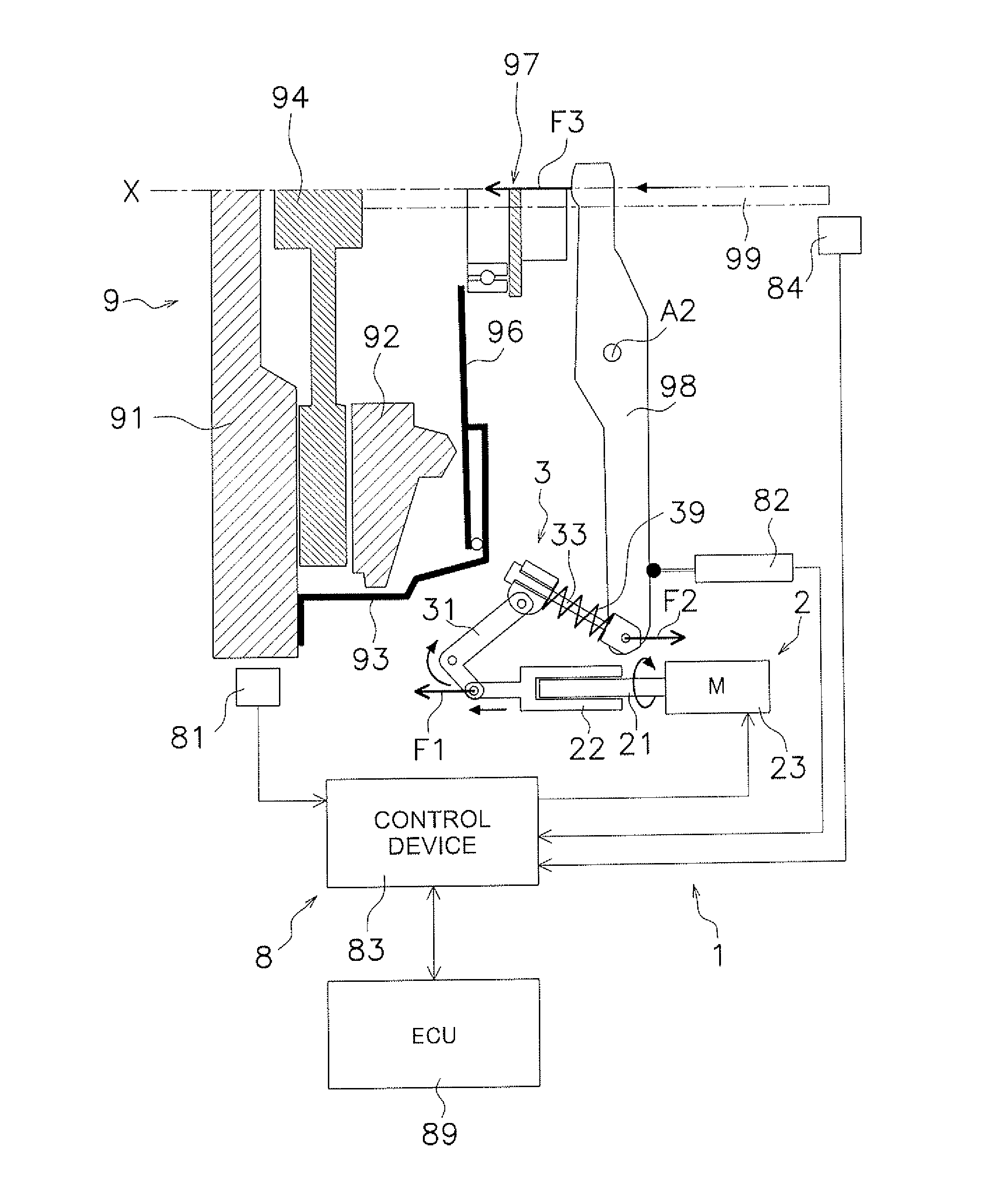
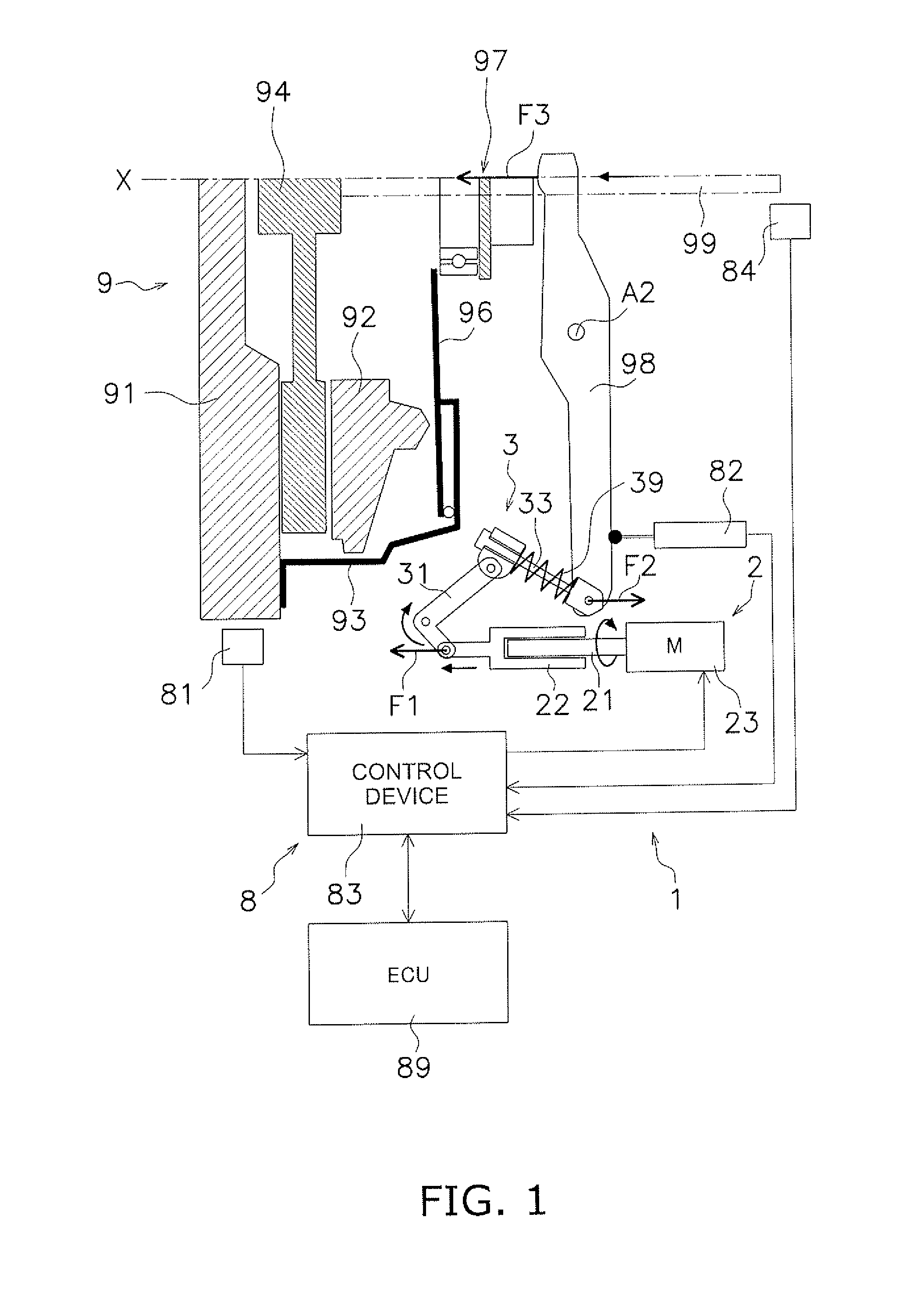
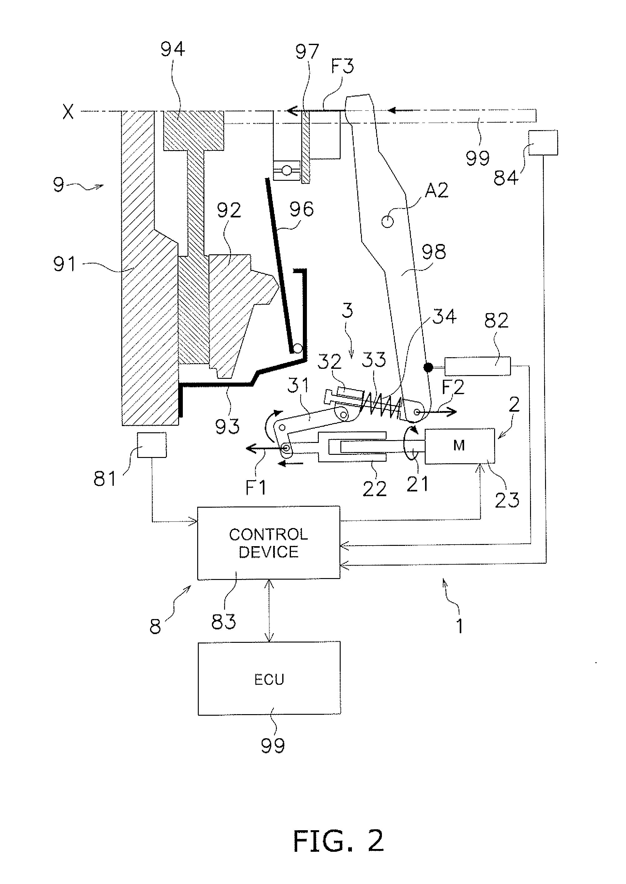
[0028]As illustrated in FIG. 1, a clutch device 9 is an exemplary device for transmitting power from an engine (not illustrated in the figure) to a transmission (not illustrated in the figure) and is, for instance, fixed to a flywheel 91 of the engine. The clutch device 9 is so-called a normal open type device. While operational force is not being applied to the clutch device 9 from a clutch operating device 1 (to be described), power is blocked from being transmitted from the engine to the transmission. The clutch operating device 1 will be described below in detail.

[0029]As illustrated in FIG. 1, the clutch device 9 includes a clutch cover 93, a pressure plate 92, a clutch disc 94, a pressure lever 96, an engaging bearing 97, and a clutch lever 98.

[0030]The clutch cover 93 is fixed to the flywheel 91. The pressure plate 92 is supported by the clutch cover 93 while being unitarily rotatable therewith and axially movable. The pressure plate 92 is coupled to the clutch cover 93...


PUM


Abstract

A clutch operating device includes a drive mechanism and a reduction mechanism. The drive mechanism generates a driving force. The reduction mechanism is a mechanism configured to amplify the driving force by reducing the driving amount to be inputted thereto from the reduction mechanism and convert the amplified driving force into an operating force of a clutch device. The reduction mechanism has a reduction ratio characteristic gradually increasing from a power blocking state to a power transmitting state of the clutch device and is allowed to adjust the reduction ratio characteristic in accordance with a state of the clutch device.

Description

CROSS-REFERENCE TO THE RELATED APPLICATIONS[0001]This U.S. national phase application claims priority to Japanese Patent Application No. 2010-155075 filed on Jul. 7, 2010. The entire disclosure of Japanese Patent Application No. 2010-155075 is hereby incorporated herein by reference.BACKGROUND[0002]1. Technical Field[0003]The present invention relates to a clutch operating device for operating a clutch device.[0004]2. Background Art[0005]In conventional manual transmissions, a clutch device is disposed between an engine and a transmission, while a shift lever of a driver's seat and the transmission are mechanically coupled through a link mechanism such as a control rod. In gear shifting, the shift lever is operated while a clutch pedal is pressed down for causing the clutch device to block transmission of power to be executed between the engine and the transmission. Therefore, when gear shifting is frequently required, a series of operations become a large burden on a driver.[0006]I...

Claims


Application Information

Patent Timeline
IPC IPC(8): F16D23/12
CPCF16D28/00F16D23/12
Inventor EGUCHI, YASUHIKOKATO, HIROAKI
Owner EXEDY CORP
Why Eureka
Try Eureka