
Systems and methods for generating power through the flow of water

a technology of system and method, applied in the field of power generation, can solve the problems of prone to errors, metering is labor intensive, and automated systems still suffer from various shortcomings

Active Publication Date: 2013-05-09
MUELLER INT LLC
View PDF7 Cites 38 Cited by
  • Summary
  • Abstract
  • Description
  • Claims
  • Application Information

AI Technical Summary

Benefits of technology

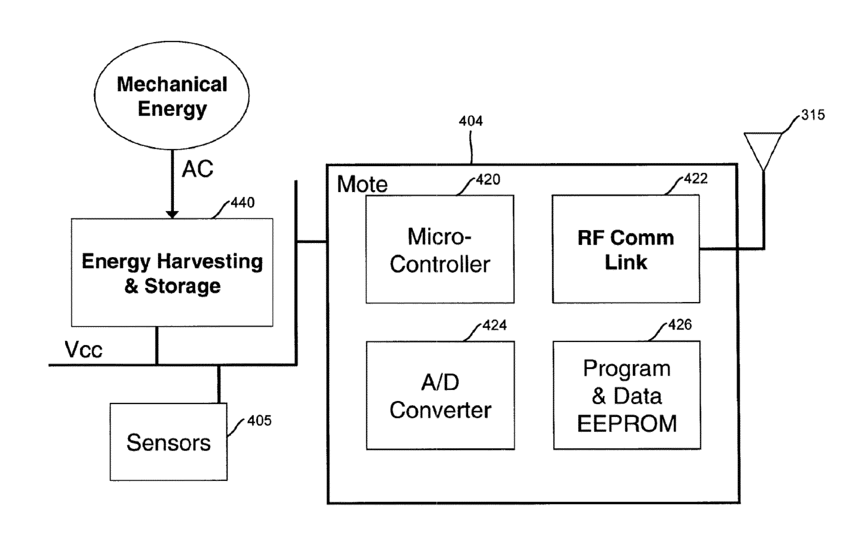
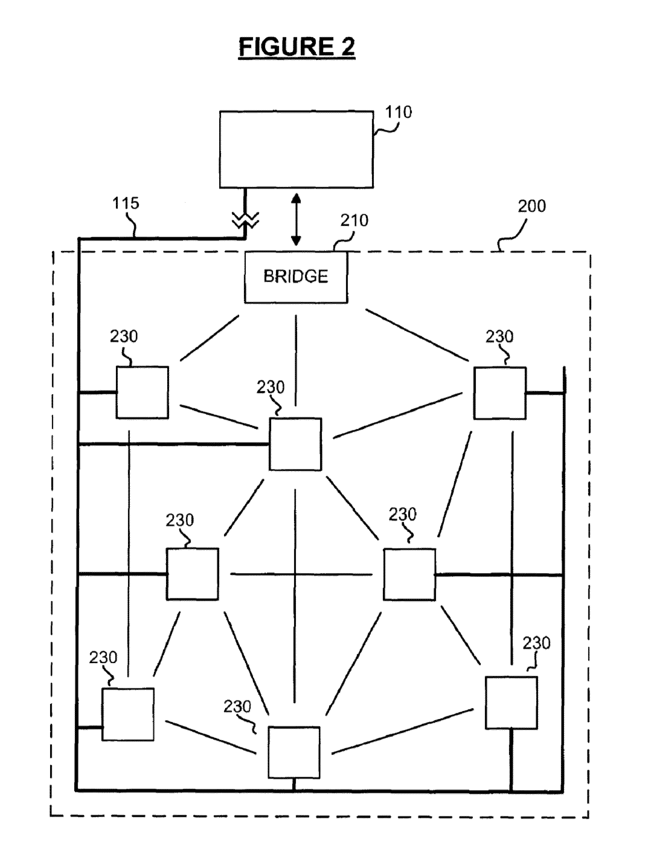
This patent describes a remote water meter monitoring system that is powered by water flow through the meter. The system includes a water meter body with a flow sensor, a power supply system, and a controller. The system also has an antenna for communication. Additionally, a wireless network that includes a central data processing system, a bridge device, and network nodes, can be used for water meter monitoring. The system or network can use a mechanical energy harnessing sub-circuit to convert water flow into electrical energy, an energy storage and delivery sub-circuit, and a water flow counting sub-circuit to detect flux changes. The system or network can also have a communication sub-circuit for two-way communication and a sensor sub-circuit for recording sensor data. The technical effects of the invention include improved efficiency and reliability of water meter monitoring, reduced maintenance costs, and improved data collection and analysis.

Problems solved by technology

Historically, metering has been a labor intensive process, and due to the manual steps required, one that is prone to error.
However, these automated systems still suffer from various shortcomings including limited battery life, limited transmission range, and lack of remote addressability, among others.

Method used


Image

  • Systems and methods for generating power through the flow of water
  • Systems and methods for generating power through the flow of water
  • Systems and methods for generating power through the flow of water

Examples


Embodiment Construction

[0058]The following description is intended to convey a thorough understanding of the embodiments described by providing a number of specific embodiments and details involving systems and methods for remote water meter monitoring. It should be appreciated, however, that the present invention is not limited to these specific embodiments and details, which are exemplary only. It is further understood that one possessing ordinary skill in the art, in light of known systems and methods, would appreciate the use of the invention for its intended purposes and benefits in any number of alternative embodiments, depending upon specific design and other needs.

[0059]As used herein, any term in the singular may be interpreted to be in the plural, and alternatively, any term in the plural may be interpreted to be in the singular.

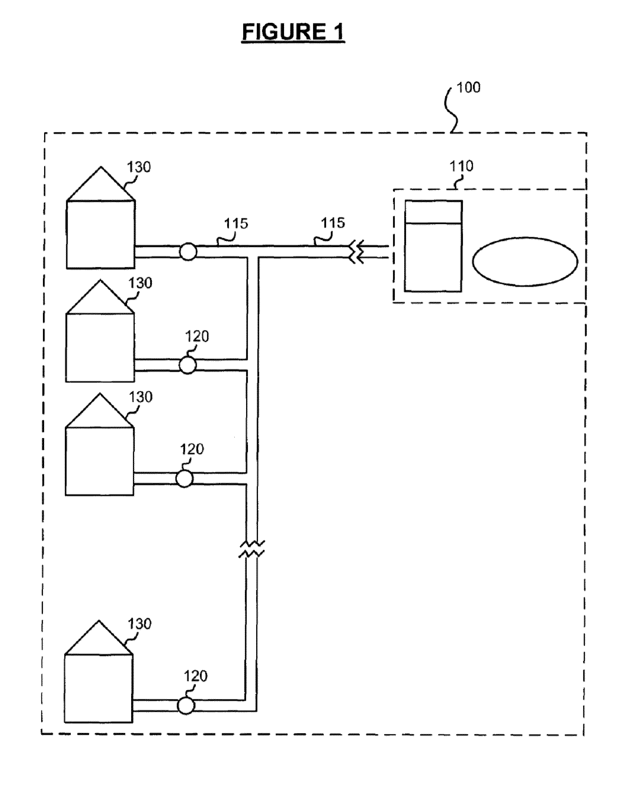
[0060]Referring now to FIG. 1, this Figure is an illustration of a typical water utility distribution network beginning with a water utility supply and terminating in a ...


PUM


Abstract

A remote water meter monitoring system is provided. A mesh network-type transceiver unit is coupled to a water meter housing having a water counting mechanism inside to transmit water consumption information as well as other sensor information, such as backflow detection, water pressure, and water metrics (e.g., residual chlorine and temperature) to a central server system via a bridge device and a corresponding mesh network. Mechanical energy from the water flowing through the water meter housing is converted to electrical energy via an energy conversion unit. An electrically powered shut off valve is remote addressable via the transceiver unit.

Description

CROSS REFERENCE TO RELATED APPLICATIONS[0001]This patent application is a Continuation-in-part (and claims priority to) U.S. patent application Ser. No. 11 / 760,200 entitled “Systems and Methods for Remote Utility Metering and Meter Monitoring,” filed on Jun. 8, 2007, which is incorporated by reference in its entirety.[0002]This patent application claims priority to U.S. Provisional Application 61 / 495,714 filed on Jun. 10, 2011 entitled “Systems and Methods for Generating Power through the Flow of Water”, which is incorporated by reference in its entirety.[0003]This patent application claims priority to both U.S. Provisional Application 60 / 811,765 filed on Jun. 8, 2006 and U.S. Provisional Application 60 / 869,501 filed on Dec. 11, 2006, both entitled “Systems and Methods for Remote Water Metering”, which are both incorporated by reference in their entirety.[0004]This application is related to U.S. patent application Ser. No. 12 / 038,151 entitled “Systems and Methods for Generating Powe...

Claims


Application Information

Patent Timeline
Patent Type & Authority Applications(United States)
IPC IPC(8): G08C17/02
CPCG08C17/02Y02B90/242Y02B90/246Y04S20/322Y04S20/42Y04S20/52G01D21/00G01F3/12G01F15/063Y02B90/248G01D4/004H04Q2209/886H04Q9/00H04Q2209/60H04W52/0229Y02B90/20Y02D30/70Y04S20/30G01D2204/45G01D4/006H02J7/34H02K7/1823H04W84/18
Inventor PITCHFORD, BARTH R.PITCHFORD, WILLIAM D.SIMON, ROBERT P.NAGEL, STEVENNARDI, BENEDICT J.SMITH, RUSSELL S.
Owner MUELLER INT LLC
Learn More