Light emitting diode road flare device

Inactive Publication Date: 2013-05-09
HUTCHINSON RONALD M +2
View PDF3 Cites 48 Cited by
  • Summary
  • Abstract
  • Description
  • Claims
  • Application Information

AI Technical Summary

Benefits of technology

[0005]The road flare device of the present invention provides an outer protective structure that is fabricated substantially in the shape of a box-like triangle having slightly rounded sides or edges. This triangular shape is critical to the intended functionality of providing a highly stable device during use. The outer protective structure comprises a number of elements. A first element is a light-transparent enclosure having the simila

Problems solved by technology

The drawback of incendiary road flares is that the flare, though bright, is short-lived.
Further, the hazard can last well beyond 10 to 20 minutes, and even hours, depending on the severity of the situation to be cleared.
For example, some prior art devices are not as visible as traditional road flares.
Others are cannot be easily positioned such that the elect

Method used


Image

  • Light emitting diode road flare device
  • Light emitting diode road flare device
  • Light emitting diode road flare device

Examples


Embodiment Construction

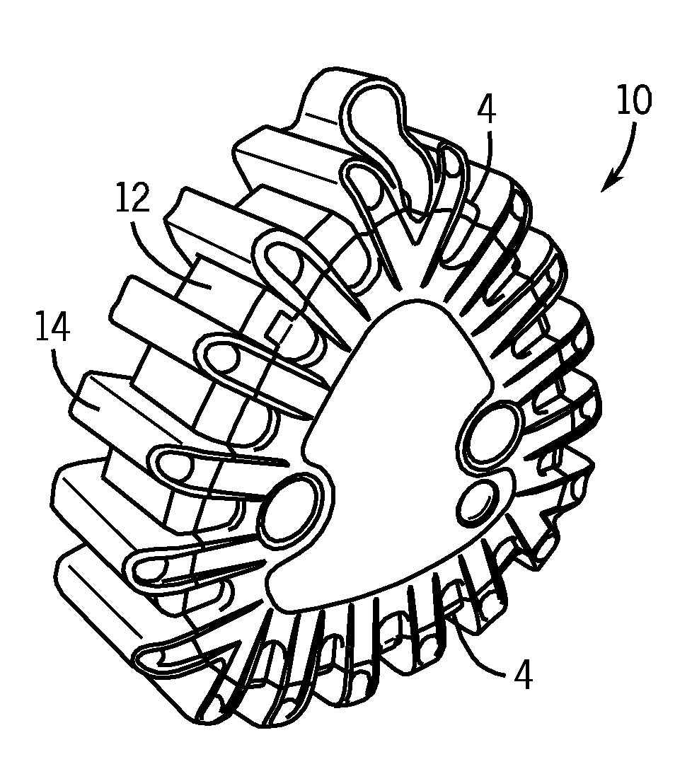
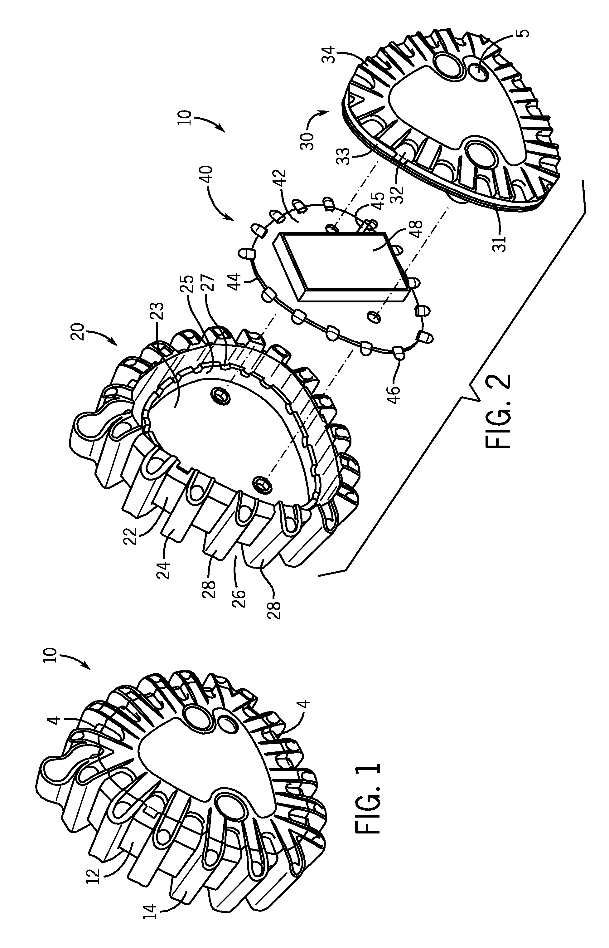
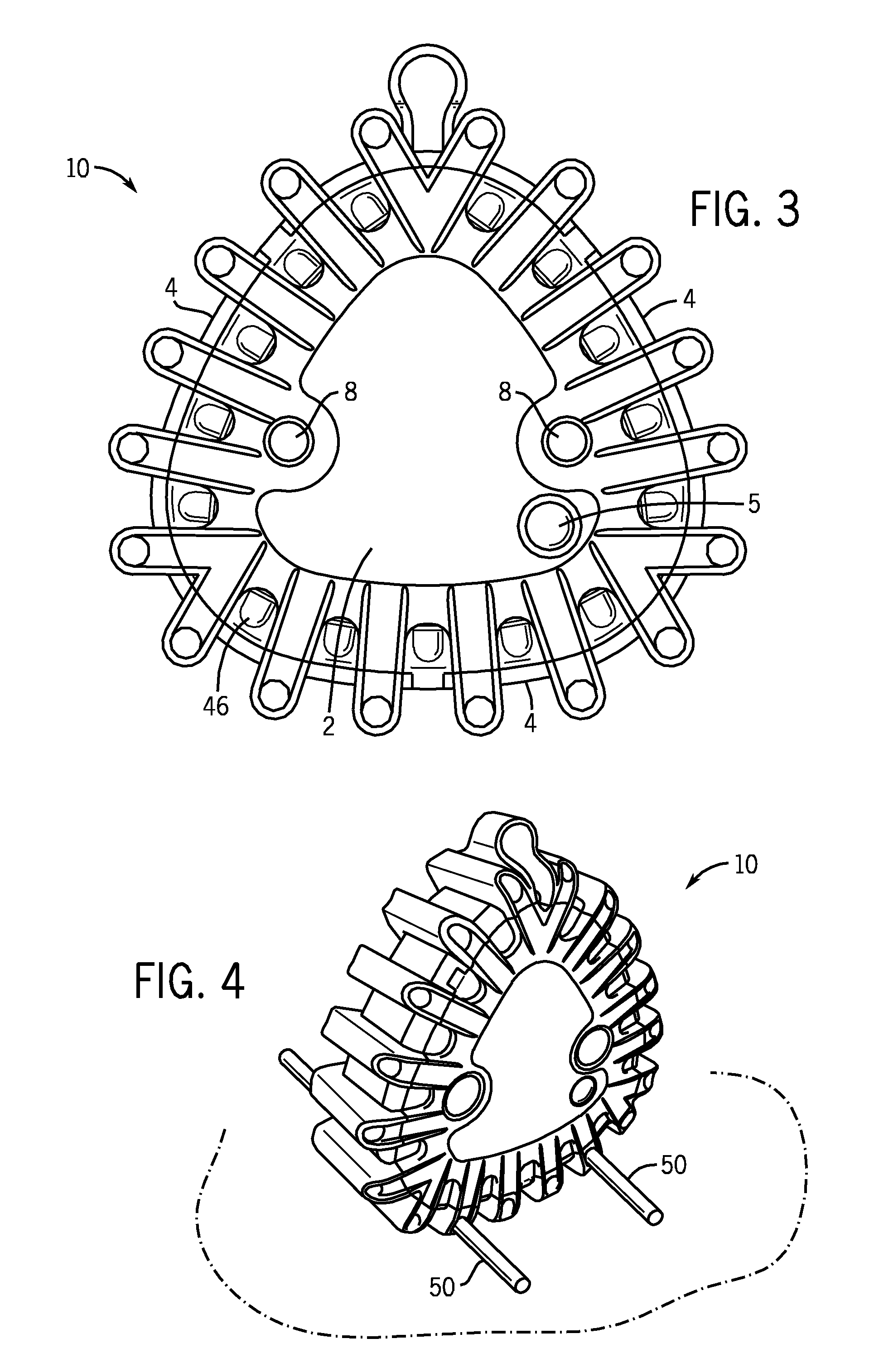
[0018]Referring now to the drawings in detail wherein like numbers represent like elements throughout, FIG. 1 illustrates a perspective view of the LED road flare device, generally identified 10, that is constructed in accordance with the present invention. Although the device 10 is identified throughout as an LED “road” flare device, it is to be understood that the device 10 may be easily used in non-vehicular applications and non-traffic hazard situations.

[0019]As shown, the LED road flare device 10 is configured as an outer protective structure 12 that is fabricated substantially in the shape of a triangular box having rounded edges. The device 10 is further configured with an overwrap structure 14 that covers a portion of the outer protective structure 12. The outer protective structure 12 comprises a number of elements and the overwrap structure 14 comprises a number of elements as well.

[0020]A first element of the outer protective structure 12 is a substantially triangular-sha...


PUM


Abstract

An LED road flare device provides an outer protective structure substantially in the form of a box-like rounded triangle. The outer protective structure comprises a first portion, which is a light-transparent enclosure having a plurality of LEDs disposed within it, and a second portion, which is a light-opaque resilient overlay comprising a front and rear face, the front and rear face being connected by a plurality of ribs defined at the outer edges of the faces. The LEDs are mounted within the transparent enclosure such that they are positioned between the ribs of the first portion to and are visible from outside the device. Electronic circuitry is provided to vary the lighting sequence of the LEDs when activated. A self-contained power supply is disposed within the transparent enclosure and means for recharging the power supply is also provided. Alternative embodiments include structure for supplemental stabilization of the device.

Description

FIELD OF THE INVENTION[0001]This invention relates generally to electronic devices that use electroluminescence or light-emitting diode (or “LED”) technology. It also relates, very generally, to incendiary road flares of the type that are used to alert drivers of a hazardous road condition. More specifically, the present invention relates to a uniquely-configured and uniquely-shaped LED road flare device, namely, an electronic road flare that is fabricated as a substantially triangular-shaped box-like structure which can be used primarily and preferably in a vertical or upright position for traffic safety or advance warning purposes. The device of the present invention can also be used for a wide variety of other safety and marking applications where a lighted warning device is required or desired.BACKGROUND OF THE INVENTION[0002]Night time marking is necessary in a wide variety of hazardous road situations. The most basic type of prior art road marking has been the use of incendiar...

Claims


Application Information

Patent Timeline
IPC IPC(8): G08G1/0955
CPCG09F13/22G09F9/33
Inventor HUTCHINSON, RONALD M.TSAI, TUSH HSEYU, CONGLUN
Owner HUTCHINSON RONALD M
Why Eureka
Try Eureka