Antenna module for vehicle

a technology for antenna modules and vehicles, applied in antenna details, electrical equipment, movable body antenna adaptation, etc., can solve the problem of significant space requirements for the installation of the lower assembly

Active Publication Date: 2013-05-09
PEIKER ACUSTIC GMBH & CO KG
View PDF5 Cites 18 Cited by
  • Summary
  • Abstract
  • Description
  • Claims
  • Application Information

AI Technical Summary

Benefits of technology

[0004]It is the object of the invention to propose an antenna module, in which only a small installation space is required below the vehicle body part to join together the two assemblies and in which in particular an internal panel of the vehicle body part, which is located below the upper assembly, does not have to be completely removed for installation or removal. Furthermore, it is an additional object of the invention to provide an antenna module, whose electrotechnical function is ensured independently of the construction of the vehicle body part.

Problems solved by technology

Such antenna modules have the disadvantage that there is a significant space requirement for the installation of the lower assembly below the vehicle body part, to be able to guide the lower assembly from below onto the upper assembly perpendicularly to the planar extension of the vehicle body part.

Method used


Image

  • Antenna module for vehicle
  • Antenna module for vehicle
  • Antenna module for vehicle

Examples


Embodiment Construction

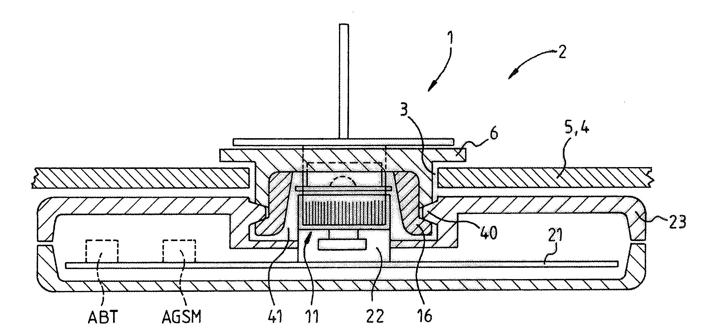
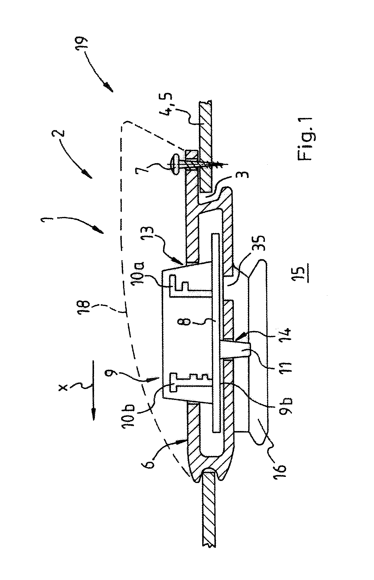
[0035]FIG. 1 shows a schematic sectional side view of an upper assembly 1 of an antenna module 2 according to the invention. The upper assembly 1 is held in a cutout 3 of a vehicle body part 4, which is shown in section, wherein the vehicle body part 4 is implemented as a vehicle body roof plate 5 and a body 6 of the first assembly 1 is additionally fixed using a fastening means 7 on the vehicle body part 4. The assembly 1 comprises, in addition to the body 6, which forms a housing, a first circuit board 8, a vertically aligned printed circuit board 9 having two antennas 10a, 10b, and a first, upper contact part 11. The contact part 11 is implemented as a multipolar contact part 11 and is arranged on a lower side 9b of the printed circuit board 9. The body 6 of the upper assembly 1 is embodied as a shielding part made of diecast zinc or a material having comparable suitability. The body 6 has a first interior 12, in which the circuit board 8 is arranged, wherein the printed circuit ...


PUM


Abstract

The invention relates to an antenna module for a vehicle, wherein an upper assembly comprises a first circuit board, wherein a lower assembly comprises a second circuit board, wherein at least one of the two assemblies is fastened on a vehicle body part of the vehicle, wherein an electrical contact part is arranged on the assembly in each case, wherein the two contact parts respectively comprise at least one antenna contact, and wherein the lower assembly is fixable on the upper assembly. In this case, the second contact part, when the lower assembly is fixed, is displaceable in a plane lying approximately parallel to the vehicle body part from a first position in a displacement direction linearly into a second position, wherein the contact parts are electrically disconnected from one another in the first position and wherein the contact parts are electrically connected in the second position.

Description

[0001]This application claims the benefit under 35 USC §119(a)-(d) of German Application No. 10 2011 117 976.7 filed Nov. 9, 2011 and German Application No. 10 2012 002 953.5 filed Feb. 16, 2012, the entireties of which are incorporated herein by reference.FIELD OF THE INVENTION[0002]The invention relates to an antenna module for a vehicle, in particular a vehicle roof antenna module.BACKGROUND OF THE INVENTION[0003]A vehicle antenna arrangement is known from DE 295 00 961 U1, which comprises an antenna module, wherein the antenna module comprises an upper assembly having at least one antenna, and a lower assembly, wherein the upper assembly comprises a first circuit board, wherein the lower assembly comprises a second circuit board, wherein at least one of the two assemblies is fastened on a vehicle body part of the vehicle, wherein a first electrical contact part is arranged on the upper assembly, wherein a second electrical contact part is arranged on the lower assembly, wherein ...

Claims


Application Information

Patent Timeline
Patent Type & Authority Applications(United States)
IPC IPC(8): H01Q1/32
CPCH01Q1/3275H01Q1/1214
Inventor BURG, ULRICHLACHNITT, JENS
Owner PEIKER ACUSTIC GMBH & CO KG
Why Eureka
Try Eureka