
Display apparatus and method of manufacturing the same

a technology of display panel and display panel, which is applied in the direction of static indicating devices, instruments, optics, etc., can solve the problems of difficult to reduce the non-display areas disposed at the left and right sides of the display panel, and achieve the effect of reducing the width of the non-display areas of the left and right side of the display panel and reducing the width of the left and right sid

Active Publication Date: 2013-05-09
SAMSUNG DISPLAY CO LTD
View PDF2 Cites 35 Cited by
  • Summary
  • Abstract
  • Description
  • Claims
  • Application Information

AI Technical Summary

Benefits of technology

The patent describes a display screen that can be made smaller without affecting its quality. This is achieved by placing the driver for controlling the display's gate at the bottom of the panel, which allows for a reduction in the width of the non-display areas on the left and right. The signal lines used for generating the gate driver's signals are also located in these areas, resulting in a narrower width for the non-display areas. Overall, this design allows for a more compact display panel.

Problems solved by technology

Accordingly, it is difficult to reduce non-display areas disposed at the left and right sides of the display panel due to the ASG circuit.

Method used


Image

  • Display apparatus and method of manufacturing the same
  • Display apparatus and method of manufacturing the same
  • Display apparatus and method of manufacturing the same

Examples


Embodiment Construction

[0048]Exemplary embodiments will be described more fully hereinafter with reference to the accompanying drawings. However, the present invention may be embodied in various different ways and should not be construed as limited to the exemplary embodiments described herein.

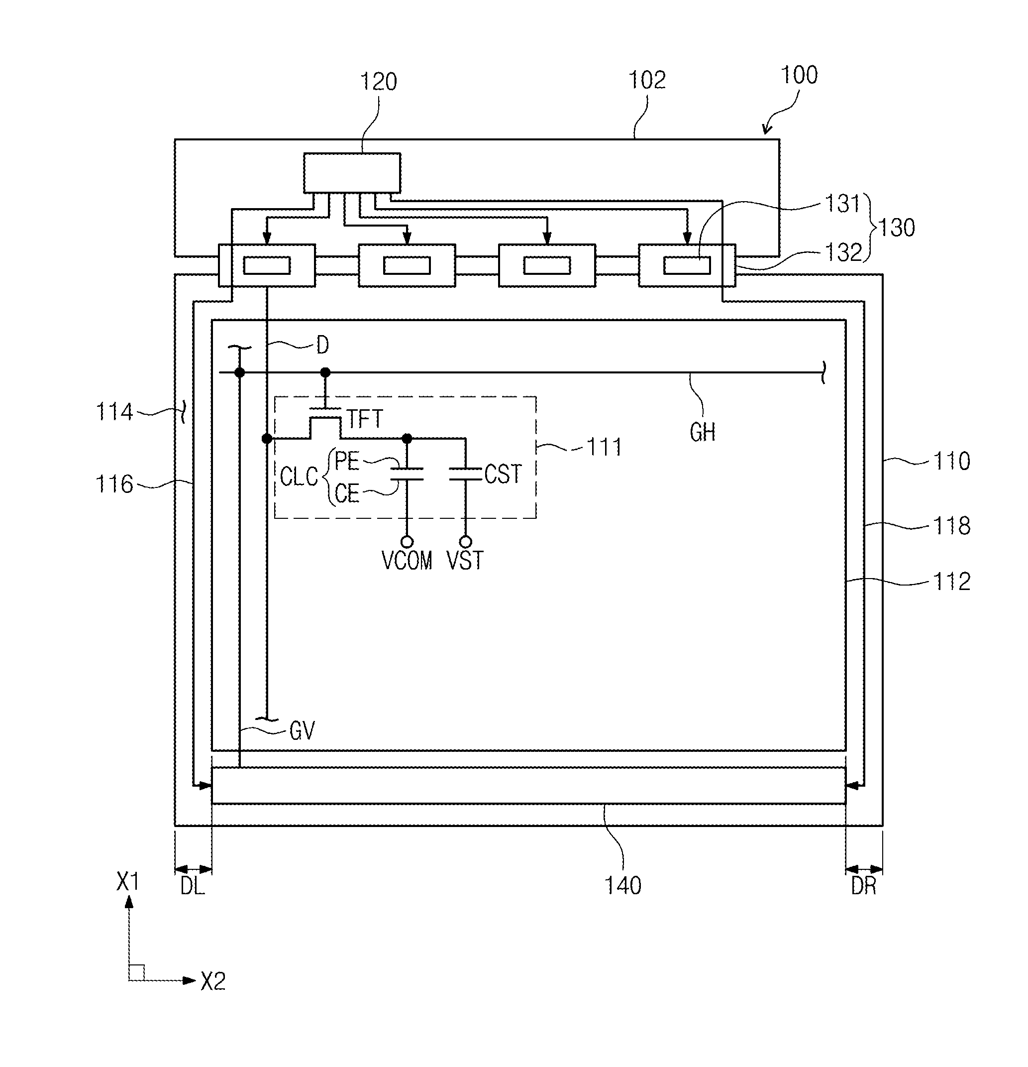
[0049]FIG. 1 is a plan view showing a display apparatus according to an exemplary embodiment.

[0050]Referring to FIG. 1, a display apparatus 100 includes a printed circuit board 102, a display panel 110, a timing controller 120, a source driver 130, and a gate driver 140. The display panel 110 includes a display area 112 and a non-display area 114.

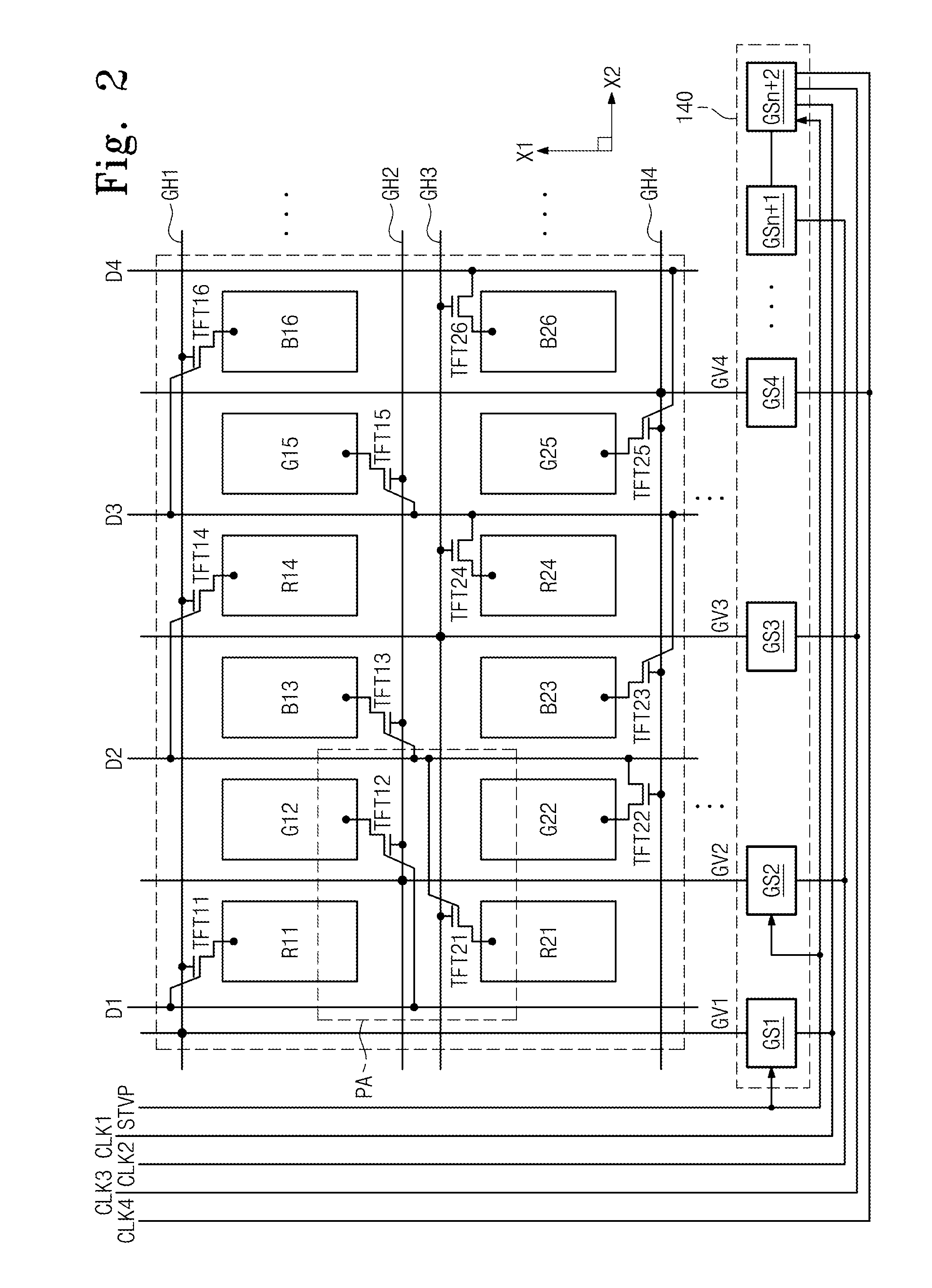
[0051]The display area 112 includes vertical gate lines GV (hereinafter, referred to as first gate lines) extended in a first direction X1, horizontal gate lines GH (hereinafter, referred to as second gate lines) extended in a second direction X2 to cross the first gate lines GV, data lines D substantially parallel to the first gate lines GV, and a plurality of pixels 111. ...


PUM


Abstract

A display apparatus includes a plurality of first gate lines extended in a first direction and disposed on a substrate on which a plurality of pixels is disposed, a plurality of second gate line extended in a second direction to cross the first gate lines, a plurality of data lines disposed substantially parallel to the first gate lines, and a first insulating layer disposed between the first gate lines and the second gate lines and provided with a plurality of via holes to expose a portion of a corresponding first gate line of the first gate lines. Each of the first gate lines makes contact with a corresponding second gate line of the second gate lines through a corresponding via hole of the via holes.

Description

CROSS-REFERENCE TO RELATED APPLICATION[0001]This application relies claims priority under 35 U.S.C §119 to Korean Patent Application No. 10-2011-0114692, filed on Nov. 4, 2011, the disclosure of which is incorporated by reference herein.BACKGROUND[0002]1. Technical Field[0003]The present invention relates to a display apparatus and a method of manufacturing the same. More particularly, the present invention relates to a display apparatus that has a reduced size while maintaining a high display quality, and a method of manufacturing the display apparatus.[0004]2. Description of the Related Art[0005]In general, a display apparatus includes a display panel and a driving circuit driving the display panel to display an image corresponding to an external input signal. The driving circuit includes a gate driving circuit and a data driving circuit. The gate driving circuit includes a gate driving IC (integrated circuit). Recently, the gate driving IC has been made with an amorphous silicon ...

Claims


Application Information

Patent Timeline
Patent Type & Authority Applications(United States)
IPC IPC(8): G06F3/038H01L33/08
CPCG09G3/3648G09G3/3674G09G2300/0426G02F1/136286G09G2320/0219G09G2320/0233G02F1/136227G09G2310/0286G02F1/1368G09G3/36
Inventor KIM, SUNGMANNA, MANHONGSONG, MIN-CHULSONG, JUNHOLEE, EUGENELIM, SUNG-HOONCHO, YOUNGJECHAE, SOOJUNG
Owner SAMSUNG DISPLAY CO LTD
Features
  • Generate Ideas
  • Intellectual Property
  • Life Sciences
  • Materials
  • Tech Scout
  • Unparalleled Data Quality
  • Higher Quality Content
  • 60% Fewer Hallucinations
Learn More