Three-dimensional image display device, three-dimensional image display method and recording medium

a three-dimensional image and display device technology, applied in the field of three-dimensional image display devices, three-dimensional image display methods, three-dimensional image display programs, and recording media, can solve problems such as difficulty in seeing a distance view, and achieve the effects of preventing excessive cross-eyedness, preventing difficulties, and preventing fatigue of eyes

Inactive Publication Date: 2013-05-09
FUJIFILM CORP
View PDF4 Cites 27 Cited by
  • Summary
  • Abstract
  • Description
  • Claims
  • Application Information

AI Technical Summary

Benefits of technology

[0035]According to the present invention, it is possible to prevent a user from becoming cross-eyed excessivel

Problems solved by technology

However, there are still disadvantages in Japanese Patent Application Laid-Open No. 2005-167310.
Displaying the most frontward object on the display plane, however, requires an

Method used


Image

  • Three-dimensional image display device, three-dimensional image display method and recording medium
  • Three-dimensional image display device, three-dimensional image display method and recording medium
  • Three-dimensional image display device, three-dimensional image display method and recording medium

Examples


first embodiment

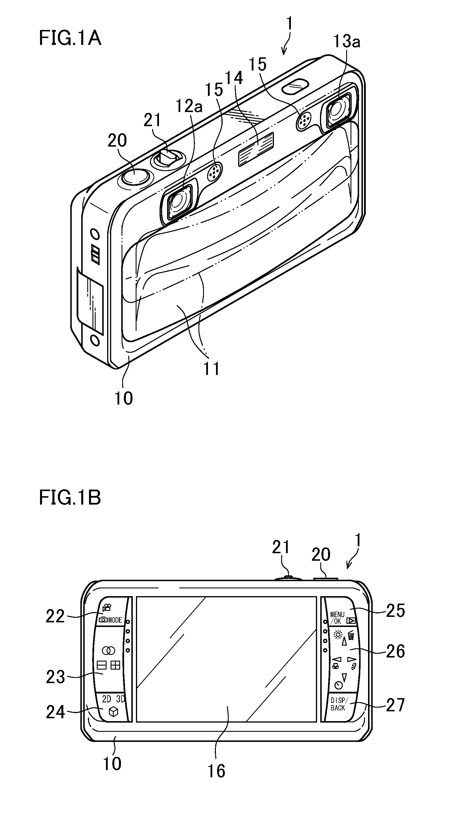
[0075]FIG. 1A and FIG. 1B are schematic views of a multi-eye digital camera 1 equipped with the three-dimensional image device according to the present invention. FIG. 1A is a front elevation view thereof and FIG. 1B is a back elevation view thereof. The multi-eye digital camera 1 is equipped with multiple (two in the example of FIG. 1A and FIG. 1B) imaging systems, and can photograph a three dimensional image (stereoscopic image) showing an identical object viewed from multiple viewpoints (two viewpoints on the right and left in the example of FIGS. 1A and 1B), and a single viewpoint image (two-dimensional image). The multi-eye digital camera 1 can record and reproduce not only still images, but also moving images and sounds.

[0076]A camera body 10 of the multi-eye digital camera 1 has a substantially rectangular parallelepiped box shape, and a barrier 11, a right imaging system 12, a left imaging system 13, a flash 14, and a microphone 15 are chiefly disposed on the front face of t...

second embodiment

[0187]In the first embodiment of the present invention, the 2D processing is performed by overlappingly displaying the images of the target object in the image for left-eye, and deleting the target object from the image for right-eye, but the 2D processing is not limited to this.

[0188]The second embodiment of the present invention overlappingly displays the images of the target object in the image for left-eye and in the image for right-eye as the 2D processing. Hereinafter, description will be provided on the multi-eye digital camera 2 of the second embodiment. The same elements as those of the first embodiment are referred to by the same reference numerals, and description thereof will be omitted.

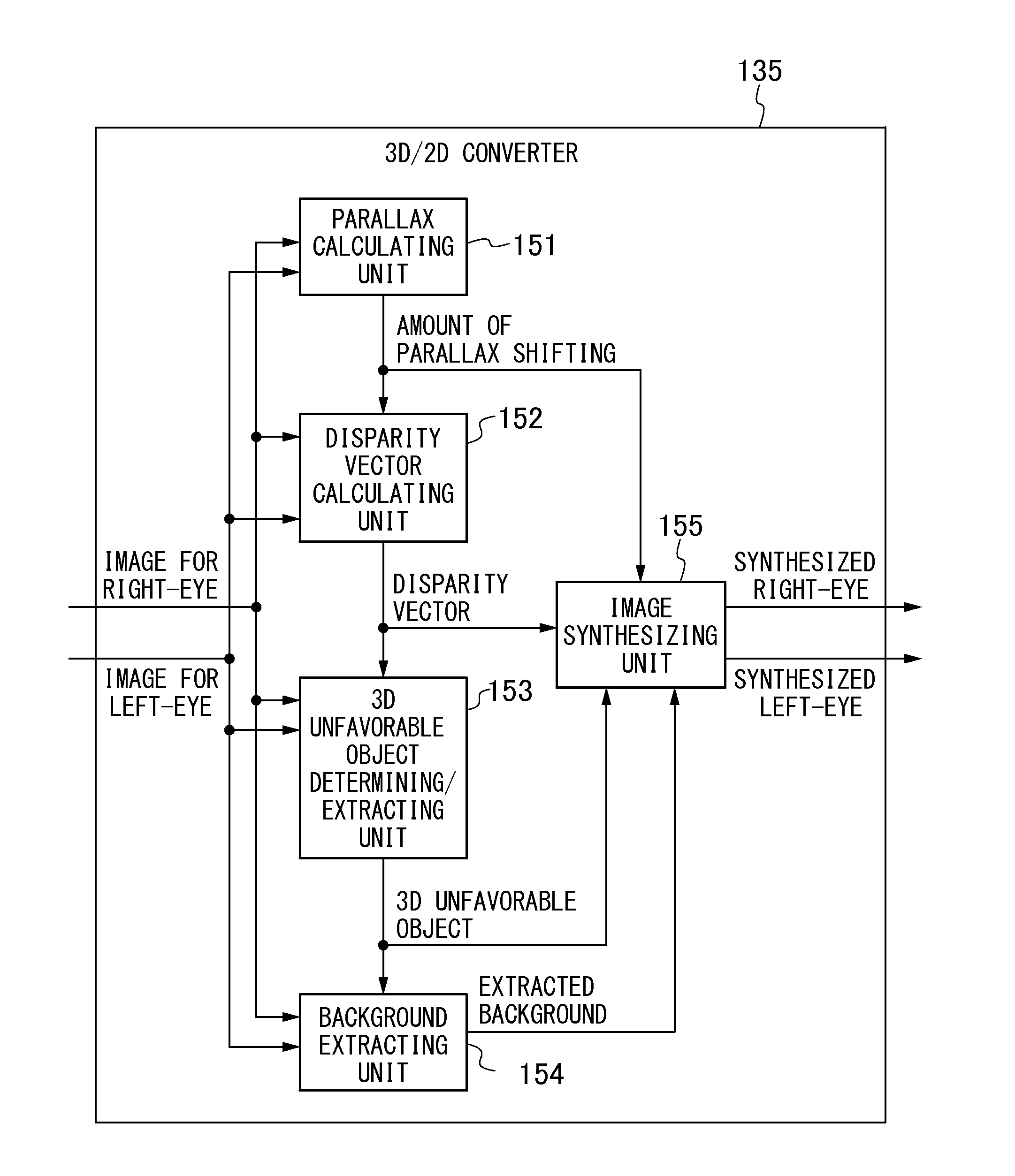
[0189]The major internal structure of the multi-eye digital camera 2 will now be described. A 3D / 2D converter 135A is the only different feature of the multi-eye digital camera 2 from the multi-eye digital camera 1, therefore, only the 3D / 2D converter 135A will be described.

[0190]FIG. 6 i...

third embodiment

[0213]In the second embodiment of the present invention, the target object processed to be semitransparent is synthesized so as to be overlappingly displayed in the image for left-eye and in the image for right-eye, but the 2D processing is not limited to this.

[0214]In 2D processing of the third embodiment of the present invention, the photographed target object is processed to be semitransparent and this semitransparent image is synthesized, so that the semitransparent images of the target object are overlappingly displayed in the image for left-eye and in the image for right-eye. Hereinafter, description will be provided on the multi-eye digital camera 3. The same elements as those of the first embodiment and the second embodiment are referred to by the same reference numerals, and description thereof will be omitted.

[0215]The major internal structure of the multi-eye digital camera 2 will now be described. A 3D / 2D converter 135B is the only different feature of the multi-eye digi...


PUM


Abstract

Among objects located more frontward than a main object, an object having a disparity vector having magnitude of a predetermined threshold value or more determined as a target object. A background image for an image for right-eye is extracted from an image for left-eye, and is combined with the image for right-eye. The target object is deleted from the image for right-eye. The target object image is combined at a position in the image for left-eye corresponding to a position of the target object in the image for right-eye to overlappingly display images of the target object in the image for left-eye. The image for right-eye from which the target object image is deleted and the image for left-eye in which the images of the target object are overlappingly displayed are three-dimensionally displayed on a monitor. Accordingly, the target object can be prevented from being viewed as a three-dimensional image.

Description

CROSS-REFERENCE TO RELATED APPLICATIONS[0001]This application is a PCT Bypass continuation application and claims the priority benefit under 35 U.S.C. §120 of PCT Application No. PCT / JP2011 / 062897 filed on Jun. 6, 2011 which application designates the U.S., and also claims the priority benefit under 35 U.S.C. §119 of Japanese Patent Application No. 2010-150066 filed on Jun. 30, 2010, which applications are all hereby incorporated by reference in their entireties.BACKGROUND OF THE INVENTION[0002]1. Field of the Invention[0003]The present invention relates to a three-dimensional image display device, a three-dimensional image display method, a three-dimensional image display program, and a recording medium, more particularly to a three-dimensional image display device, a three-dimensional image display method and a recording medium capable of displaying a three-dimensional image in consideration of fatigue of a user's eyes.[0004]2. Description of the Related Art[0005]An example of a r...

Claims


Application Information

Patent Timeline
IPC IPC(8): H04N13/00
CPCG03B35/18H04N13/0022H04N13/0033H04N2013/0081H04N13/0014H04N13/0018H04N13/0011H04N13/111H04N13/117H04N13/122H04N13/128H04N13/144
Inventor NAKAMARU, FUMIO
Owner FUJIFILM CORP
Why Eureka
Try Eureka