Auto-stereoscopic multi-dimensional display component and display thereof

a multi-dimensional display and display component technology, applied in optics, instruments, electrical devices, etc., can solve the problems of crosstalk and moiré effect, crosstalk and overlap patterns still exist, and the effect of overlapping

Inactive Publication Date: 2013-05-09
IND TECH RES INST
View PDF0 Cites 11 Cited by
  • Summary
  • Abstract
  • Description
  • Claims
  • Application Information

AI Technical Summary

Benefits of technology

[0021]The detailed characteristics and advantages of the disclosure are described in the following embodiments in details, the techniques of the disclosure can be easily understood and embodied by a person of average skill in the art, and the related objects and advantages of the disclosure can be easily understood by a person of average skill in the art by referring to the contents, the claims and the accompanying drawings disclosed in the specifications.

Problems solved by technology

Even though the problem with the reduced brilliance is improved by this method, problems with crosstalk of images and Moiré effect still exist.
Even though the auto stereoscopic technology is being researched and developed continuously, the aforementioned problems with brilliance, crosstalk and overlapping patterns still exist.

Method used


Image

  • Auto-stereoscopic multi-dimensional display component and display thereof
  • Auto-stereoscopic multi-dimensional display component and display thereof
  • Auto-stereoscopic multi-dimensional display component and display thereof

Examples


first embodiment

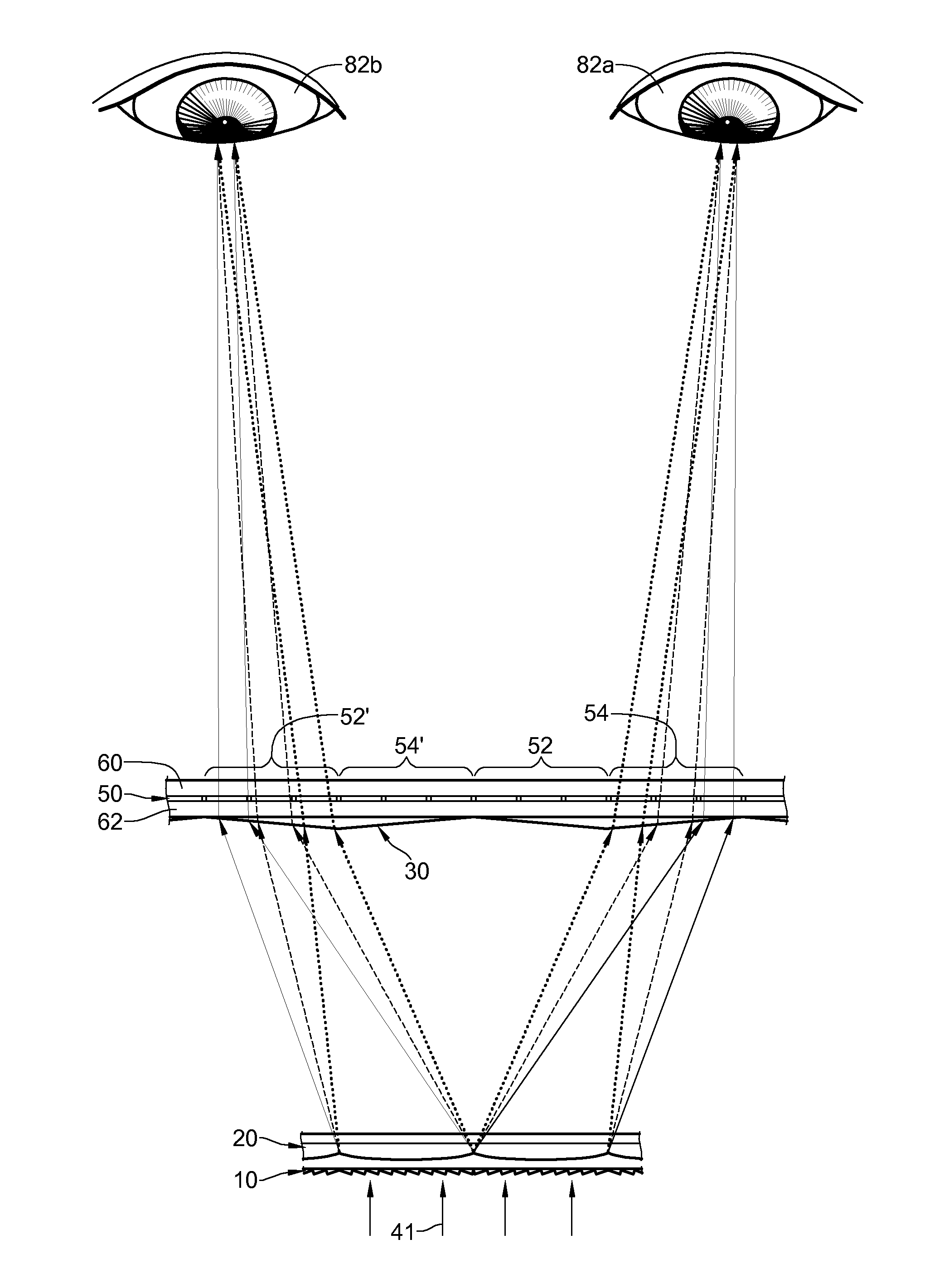
[0042]Referring to FIG. 3A, which is an illustration of optical paths of an auto-stereoscopic stereo display effect of an auto-stereoscopic multi-dimensional display component according to the disclosure being applied in a liquid crystal module. The optical paths in FIG. 3A are illustrated in a way that red lights are indicated by solid lines, green lights are indicated by broken lines, while blue lights are indicated by dotted lines. Only four adjacent pixels 52, 54, 52′ and 54′ are shown in FIG. 3A; images presented by the first pixels 52 and 52′ are a first portion of a stereo-image, while images presented by the second pixels 54 and 54′ are a second portion of the stereo-image. Therefore, after the backlight source 41 is sequentially split, converged and refracted by the color grating 10, the convergent element 20 and the refractive element 30 sequentially, then the two aforementioned portions of the stereo-image can be projected to a viewer's left and right eyes 82a and 82b res...

third embodiment

[0047]In the third embodiment, the convergent element 20 receives and converges the first, the second and the third waveband lights 42R, 44R, 42G, 44G, 42B and 44B, so that the first converged waveband lights 42R and 44R pass through the first corresponding sub-pixels 52R and 54R respectively, the second converged waveband lights 42G and44G pass through the second corresponding sub-pixels 52G and 54G respectively, and the third converged waveband lights 42B and 44B pass through the third corresponding sub-pixels 52B and 54B respectively. The included angles 01 and 02 between the first waveband lights 42R and 44R, the second waveband lights 42G and 44G and the third waveband lights 42B and 44B after split by the color grating 10 can be less than 1 degree. The color grating 10 comprises a plurality of micro prism arrays, and a period of each of the micro prism arrays is between 6 microns and 60 microns.

[0048]Referring to FIG. 6, which is a structural view of a fourth embodiment of an ...


PUM

PropertyMeasurementUnit
included angleaaaaaaaaaa
heightaaaaaaaaaa

Abstract

An auto-stereoscopic multi-dimensional display component is applicable for receiving and splitting a backlight source into waveband lights, and the waveband lights can be refracted to different positions of colored pixels. The multi-dimensional display component comprises a color grating element and a light guiding element; wherein the color grating element is configured to split and refract the backlight source, while the light guiding element emits the waveband lights towards the corresponding pixel positions. When the auto-stereoscopic multi-dimensional display component is applied in an image display device, it becomes a device of different dimensions according to its spectroscopical position.

Description

CROSS-REFERENCE TO RELATED APPLICATIONS[0001]This non-provisional application claims priority under 35 U.S.C. §119(a) on Patent Application No(s). 100140604 filed in Taiwan, R.O.C. on Nov. 7, 2011, the entire contents of which are hereby incorporated by reference.BACKGROUND[0002]1. Technical Field[0003]The present disclosure relates to a multi-dimensional display component and more particularly to an auto-stereoscopic multi-dimensional display component.[0004]2. Related Art[0005]Three-dimensional display technology is flourishing as it is becoming more popular and commercialized. An auto-stereoscopic technology is a type of three-dimensional display technologies, and it provides a convenience that viewers do not need to wear any auxiliary tools to view images presented by the auto-stereoscopic technology. Many are dedicated to researching the technology.[0006]Most conventional auto-stereoscopic displays use parallactic barrier or lenticular design, and the former employs a periodic ...

Claims


Application Information

Patent Timeline
Patent Type & Authority Applications(United States)
IPC IPC(8): G02F1/13357G02B30/27
CPCH04N13/0409G02B27/2214H04N13/0422H04N13/324H04N13/31G02B30/27
Inventor LIN, HUI-HSIUNGCHEN, CHIEN-YUEDENG, QING-LONG
Owner IND TECH RES INST
Why Eureka
Try Eureka