Light Emitting Device

a technology of light emitting device and light source, which is applied in the direction of lighting and heating apparatus, lighting source combinations, lighting applications, etc., can solve the problems of desirably inconspicuous signaling lamps, external light incident on transparent globes that are liable to pass, etc., to prevent lighting misrecognition, facilitate the assembly of light emitting devices, and improve contrast

Inactive Publication Date: 2013-05-09
PATO RAITO KK
View PDF14 Cites 15 Cited by
  • Summary
  • Abstract
  • Description
  • Claims
  • Application Information

AI Technical Summary

Benefits of technology

[0012]The half mirror may be partitioned into a plurality of portions by a nontransparent portion or a half mirror having a higher reflectance according to an accommodated light source position and a light emitting direction. This improves a contrast between the lighting state and a blinking state of the light source.
[0013]In the present invention, the inner lens may have a tubular shape to surround the light source. This facilitates the assembling of the light emitting device. Further, a space surrounded by the half mirror can be provided into which the external light is less liable to intrude. That is, the contrast between the lighting state and the unlighting state can be provided, thereby substantially preventing the lighting misrecognition which may otherwise occur due to the external light.
[0014]In the present invention, the light emitting device may include a case to which the inner lens is attached, and the case may retain a lower portion of the tubular inner lens in a self-standing state and have a lamp retaining portion which prevents the external light from intruding into the inner lens. This facilitates the assembling of the light emitting device. Further, the space surrounded by the half mirror can be provided into which the external light is less liable to intrude. That is, the contrast between the lighting state and the unlighting state can be provided, thereby substantially preventing the lighting misrecognition which may o...

Problems solved by technology

With a signaling lamp of PTL1, however, external light incident on the transparent globe is liable to pass through the transparent globe to be further incident on the reflection member.
This may result in ...

Method used


Image

  • Light Emitting Device
  • Light Emitting Device
  • Light Emitting Device

Examples


first embodiment

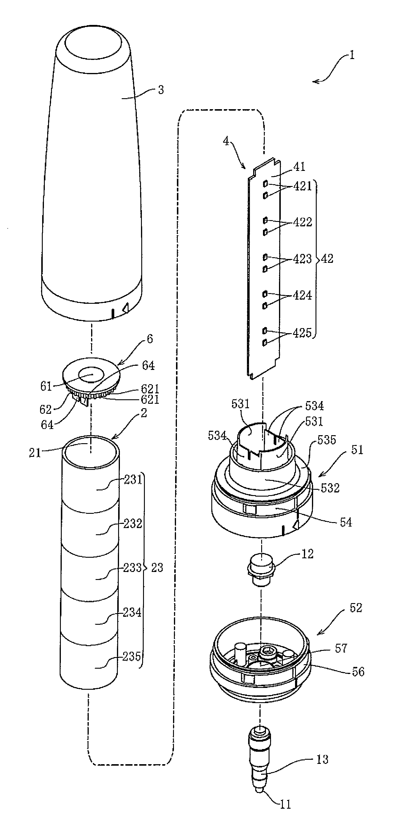
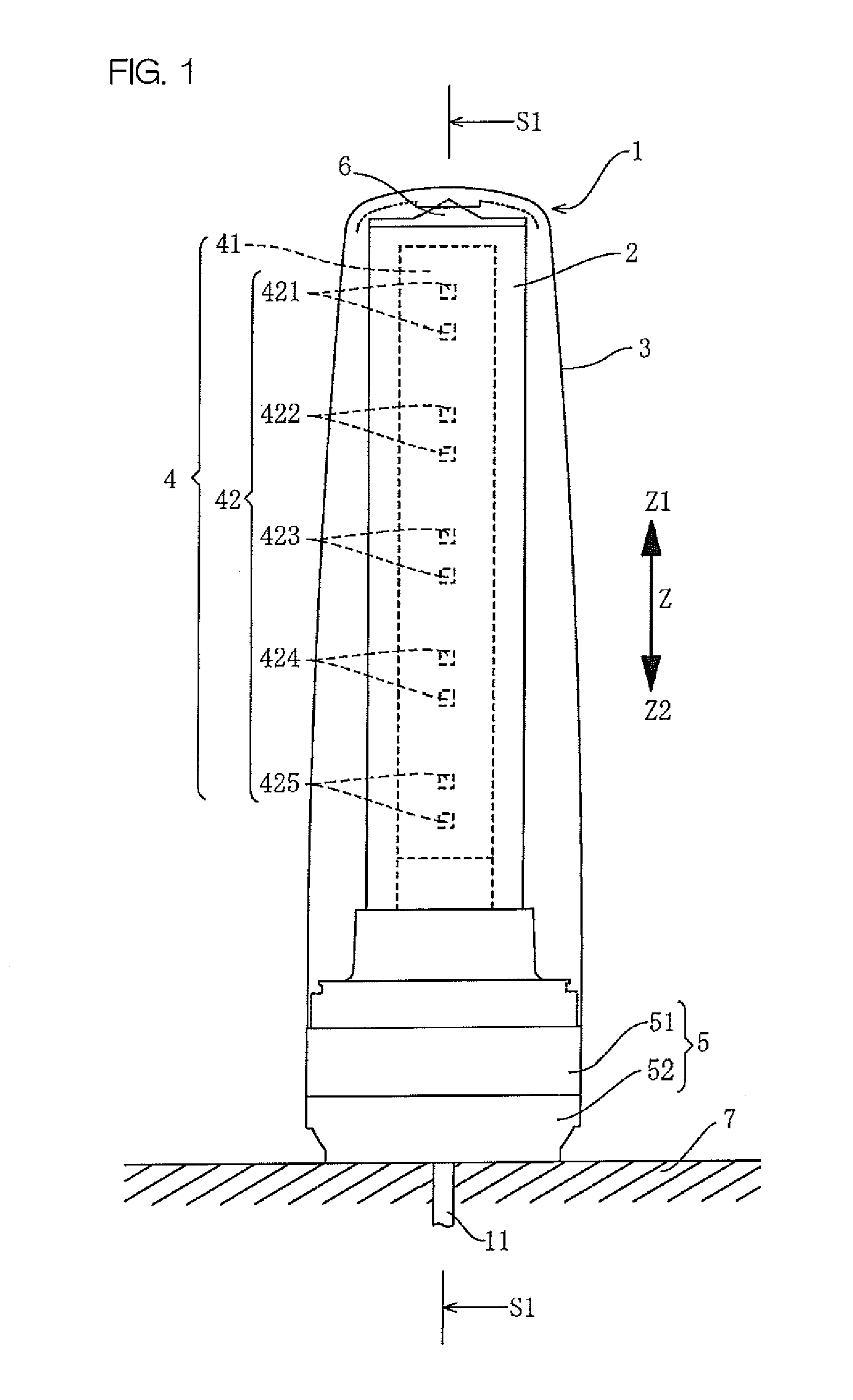
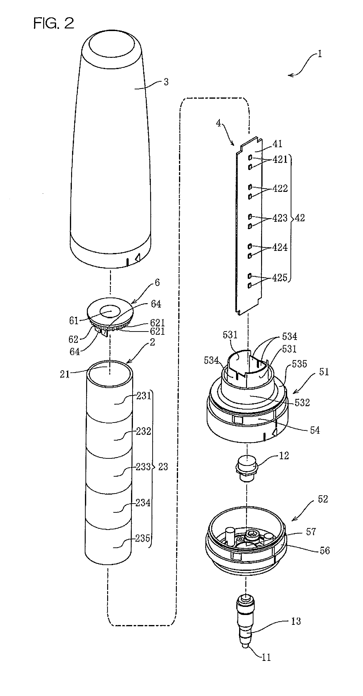
[0027]FIG. 1 is a front view of a light emitting device 1 according to the present invention. Referring to FIG. 1, the light emitting device 1 has a column shape elongated in one direction. The light emitting device 1 is mounted on an upper surface of an object (e.g., an equipment machine 7) with its longitudinal axis aligned with a vertical direction Z (an upward direction and a downward direction indicated by arrows Z1 and Z2, respectively) to function as a signaling lamp.

[0028]The inventive light emitting device can be employed not only as the signaling device but also as an indicator such as a lighting device, a rotating warning lamp or a road sign. In this embodiment, the signaling lamp will be described according to the present invention by way of example.

[0029]The light emitting device 1 includes a case 5 for mounting the light emitting device 1 on the equipment machine 7, a light emitting member 4 supported by the case 5, an inner lens 2 provided around the light emitting me...

third embodiment

[0057]In the third embodiment, the outer cover 3A is described as a part of the light emitting device 1B. Alternatively, a portion of the light emitting device 1B except for the outer cover 3A may be embedded in the equipment machine 7A, and the outer cover 3A may be defined by a surface panel of the equipment machine. Where the light emitting device 1B does not require water-proofing and drip-proofing, the outer cover 3A may be obviated. In this case, the exterior appearance of the light emitting device 1B can be assimilated to the exterior appearance of the equipment machine 7A on which the light emitting device 1B is mounted. This increases the sense of unity between the light emitting device1B and the equipment machine, making the light emitting device 1B less conspicuous in the unlighting state.

[0058]Next, a light emitting device 1C according to a fourth embodiment will be described. FIG. 8 is a diagram illustrating the light emitting device according to the fourth embodiment. ...


PUM


Abstract

A light emitting device which is substantially free from misrecognition occurring due to external light and is less conspicuous. The light emitting device includes an inner lens subjected to a half mirror treatment and provided around a light emitting member. The inner lens is tubular, and has a half mirror formed on an outer peripheral surface thereof by metal coating. The inner lens surrounds the light emitting member, and its lower portion is retained by a case. An engagement cover is attached to an upper portion of the inner lens. Thus, the inner lens is fixed to the outer cover, and prevents external light from intruding into the inner lens.

Description

FIELD OF THE INVENTION[0001]The present invention relates to a light emitting device.BACKGROUND OF THE INVENTION[0002]A light emitting device, particularly a signaling lamp employing the light emitting device, includes one or more light sources (LEDs or the like) provided therein, and a reflection member for reflecting light emitted from the light sources. The light emitting device further includes a transparent globe covering the light sources and the reflection member, and a divergent lens provided on a surface of the globe for diverging light passing therethrough. The light sources may be adapted to emit a plurality of color light beams.[0003]PTL1: JP-2000-353401A[0004]With a signaling lamp of PTL1, however, external light incident on the transparent globe is liable to pass through the transparent globe to be further incident on the reflection member. Then, the incident light is reflected outside the globe. This may result in misrecognition such that, though the internal light so...

Claims


Application Information

Patent Timeline
IPC IPC(8): F21V13/04
CPCF21W2111/00F21V13/04F21S8/00F21V7/22F21S8/033F21V7/043F21Y2103/003F21Y2101/02F21W2131/403F21Y2113/005F21V13/02F21Y2103/10F21Y2115/10F21Y2113/13F21Y2107/90F21V7/24F21Y2103/00
Inventor SHIGEMATSU, DAISUKEMASHIRO, KAZUKI
Owner PATO RAITO KK
Why Eureka
Try Eureka