System and Method for Interference Management in Cellular Networks

Active Publication Date: 2013-05-09
FUTUREWEI TECH INC
View PDF33 Cites 57 Cited by
  • Summary
  • Abstract
  • Description
  • Claims
  • Application Information

AI Technical Summary

Problems solved by technology

While user equipments (UEs) are typically aware of the location/presence of CRS symbols transmitted by their respecti

Method used


Image

  • System and Method for Interference Management in Cellular Networks
  • System and Method for Interference Management in Cellular Networks
  • System and Method for Interference Management in Cellular Networks

Examples


Embodiment Construction

[0019]The making and using of the presently disclosed embodiments are discussed in detail below. It should be appreciated, however, that the present disclosure provides many applicable inventive concepts that can be embodied in a wide variety of specific contexts. The specific embodiments discussed are merely illustrative of specific ways to make and use embodiments of this disclosure, and do not limit the scope of this disclosure.

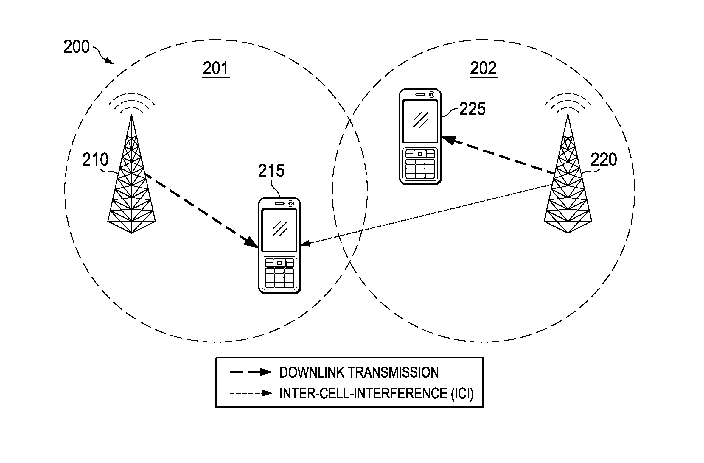
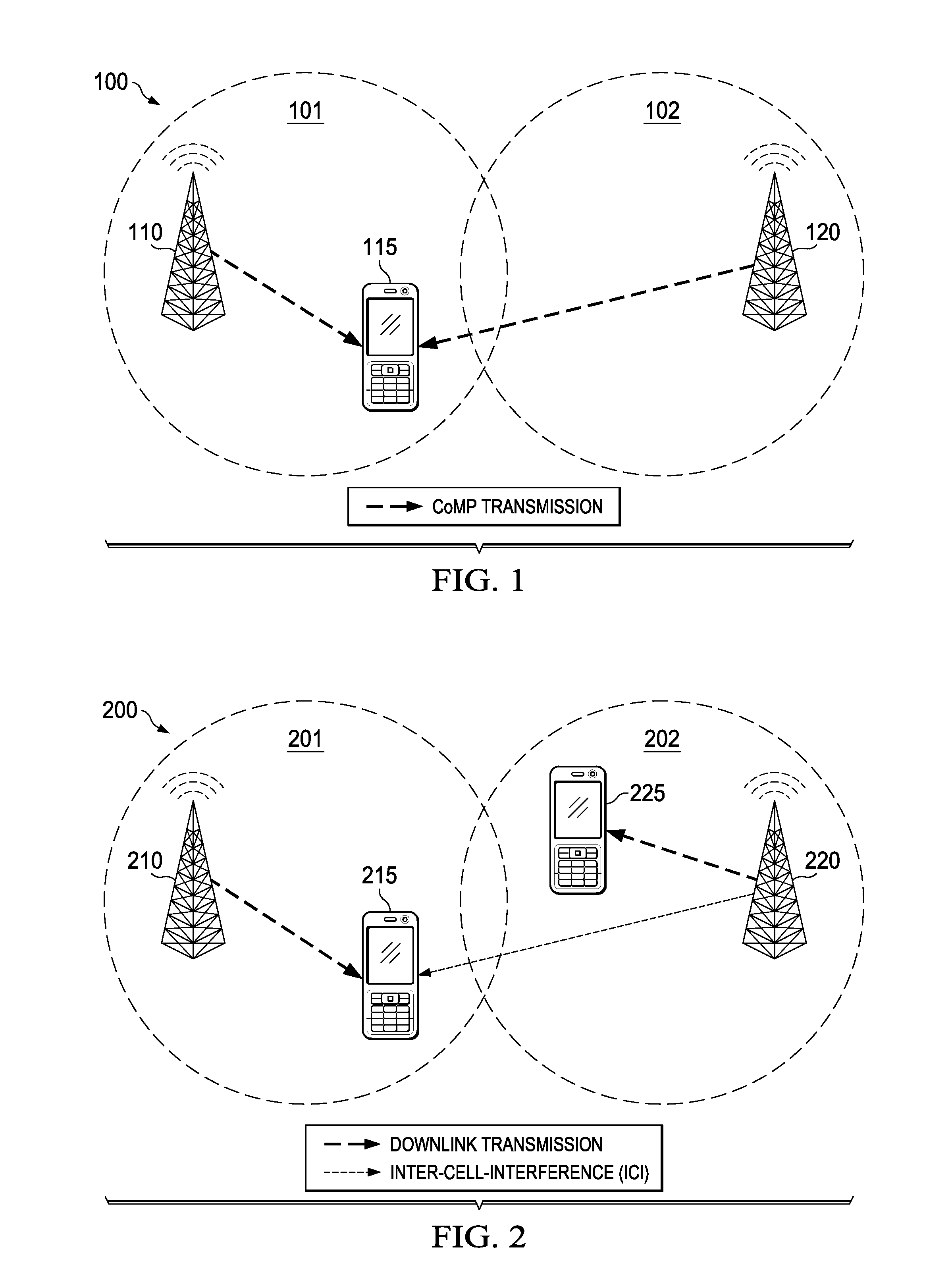
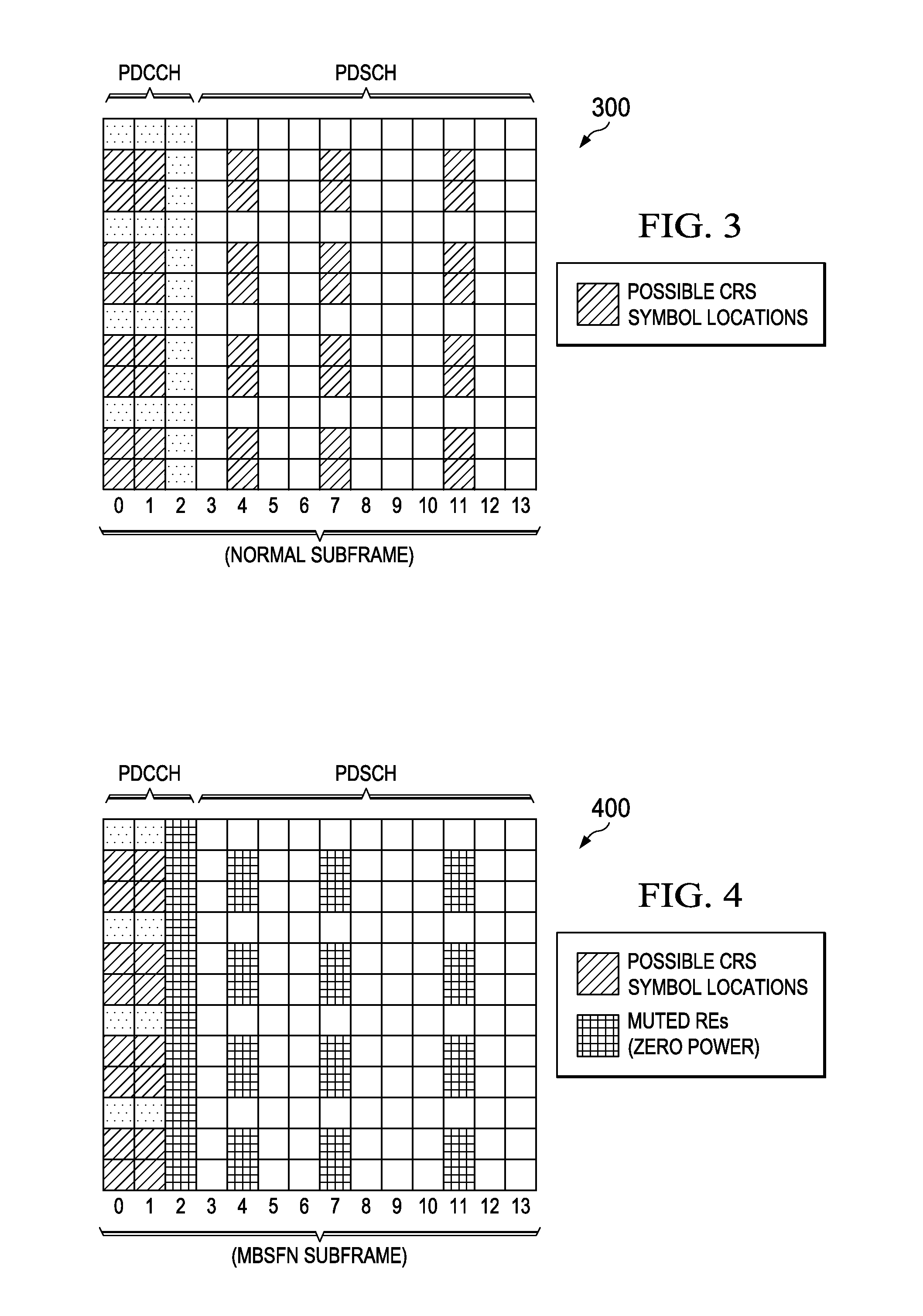
[0020]Knowledge relating to CRS symbols transmitted by neighboring cells is beneficial for served UEs receiving cooperative transmissions as well as non-cooperative transmissions. One technique for communicating CRS parameters of neighboring cell(s) to a served UE is to communicate the number of CRS antenna ports (e.g., one, two, or four) and the frequency shifts of the neighboring cell to the UE. However, this technique ignores the possibility that CRS symbols of a neighboring cell are excluded from the PDSCH region of a downlink subframe, as might be the...


PUM


Abstract

Notifying served user equipments (UEs) of the presence or absence of cell-specific reference signal (CRS) symbols transmitted by neighboring base stations in the physical downlink shared channel (PDSCH) region of a subframe can be achieved through various of signaling techniques. The served UE may be notified by communicating a one or multi-bit indicator in a physical layer signaling channel of the serving cell, such as the physical downlink control channel (PDCCH) of the subframe. Alternatively, the served UE may be notified through higher layer signaling.

Description

[0001]This application claims the benefit of U.S. Provisional Application No. 61 / 557,323 filed on Nov. 8, 2011, entitled “System and Method for Interference Management in Cellular Networks,” which is incorporated herein by reference as if reproduced in its entirety.TECHNICAL FIELD[0002]The present disclosure relates to wireless communications, and, in particular embodiments, to systems and methods for interference management in cellular networks.BACKGROUND[0003]In Third Generation Partnership Project (3GPP) Long Term Evolution (LTE) networks, cell-specific reference signal (CRS) symbols are included in downlink subframes to provide channel estimation for demodulation and downlink channel quality measurement. The number and location of the CRS symbols within a given subframe or resource block (RB) varies depending on the transmission mode of the signal, and more specifically, on the number of CRS antenna ports (e.g., one, two, or four) used to perform the data transmission. While use...

Claims


Application Information

Patent Timeline
IPC IPC(8): H04W72/04H04H20/71
CPCH04L5/0023H04L5/0053H04L5/0048H04W72/23H04H20/57H04L5/005H04W24/02H04W36/20H04W88/02H04W88/12
Inventor MAZZARESE, DAVID JEAN-MARIELI, QIANGYU, ZHENGXIAO, WEIMINCLASSON, BRIAN
Owner FUTUREWEI TECH INC
Why Eureka
Try Eureka