Airborne energy generation and distribution

a technology for airborne energy and distribution, applied in the direction of photovoltaics, steam engine plants, motors, etc., can solve the problems of mobile energy users and respective locations, difficult to apply to demand-driven applications, and none of the solutions disclosed in the prior art solve the problem

Inactive Publication Date: 2013-05-16
CARDOSO PAULO ALEXANDRE
View PDF1 Cites 8 Cited by
  • Summary
  • Abstract
  • Description
  • Claims
  • Application Information

AI Technical Summary

Benefits of technology

[0008]The present invention addresses the problem of organizing operations of airships and energy systems, i.e. airborne and ground processes, evolution in time, control structure, key design aspects of devices and installations involved in such processes, in such ways and scales that airborne renewable energy generation and distribution becomes of economical advantage across different prospective applications, while at minimal environmental impacts (land and airspace use, visual and noise impacts, wildlife and public health hazards).

Problems solved by technology

Moreover, depending on the actual technology and altitude range, such tethered wind energy devices do not exclude the need for propulsion means or interruption of operations under adverse weather.
On the other hand, all these systems follow a supply-centric model, whereby all generated energy is transmitted (via the tethering cable) to one, eventually remote location for further grid distribution, therefore being difficult to apply to demand-driven applications, mobile energy users and respective locations.
None of the solutions disclosed in the prior art solves the problem of minimizing the volume of airspace occupied by a plurality of air vehicles, in particular of the airship type, in parallel with the maximization of energy generation and distribution to a given location.

Method used


Image

  • Airborne energy generation and distribution
  • Airborne energy generation and distribution
  • Airborne energy generation and distribution

Examples


first embodiment

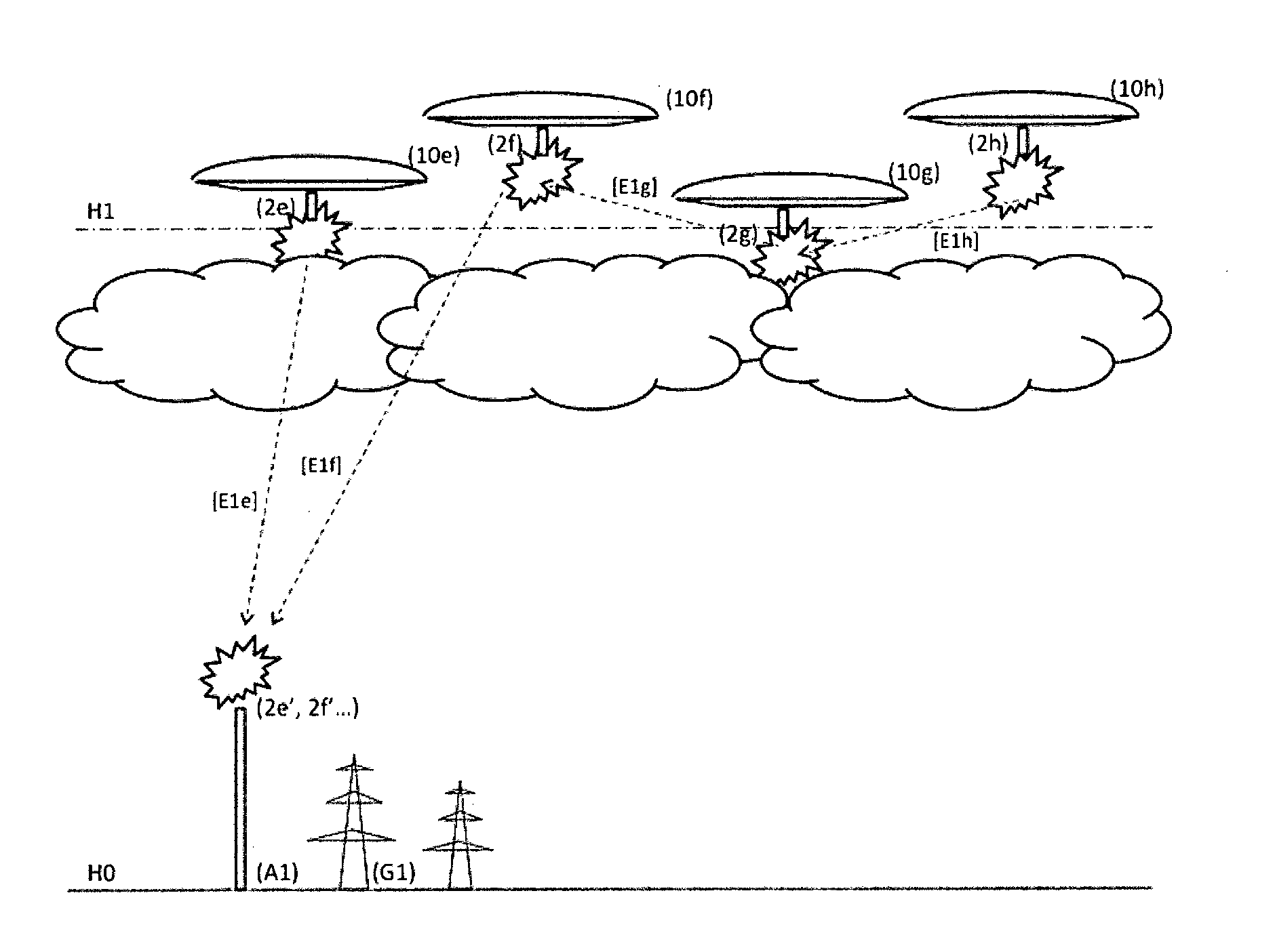
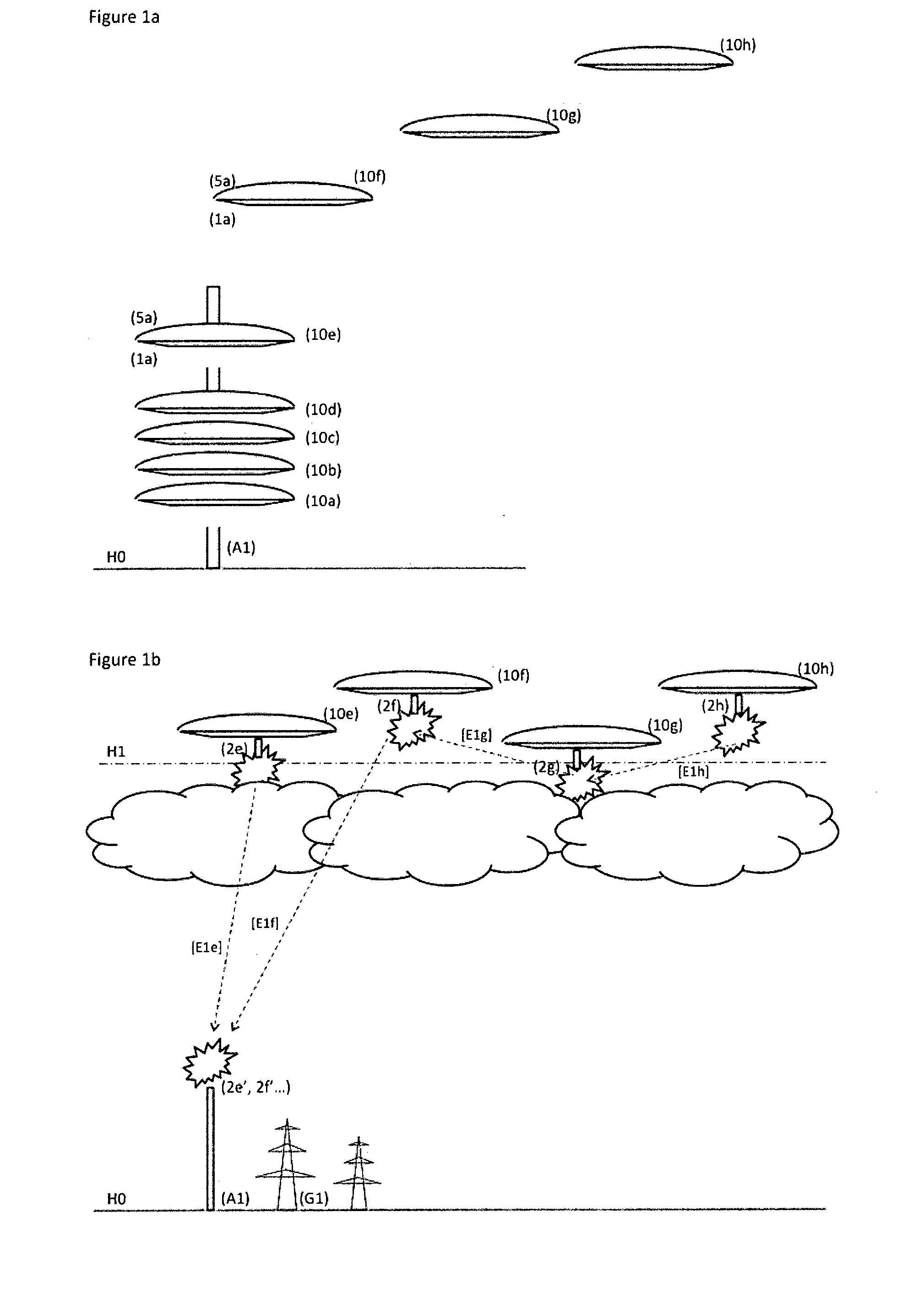
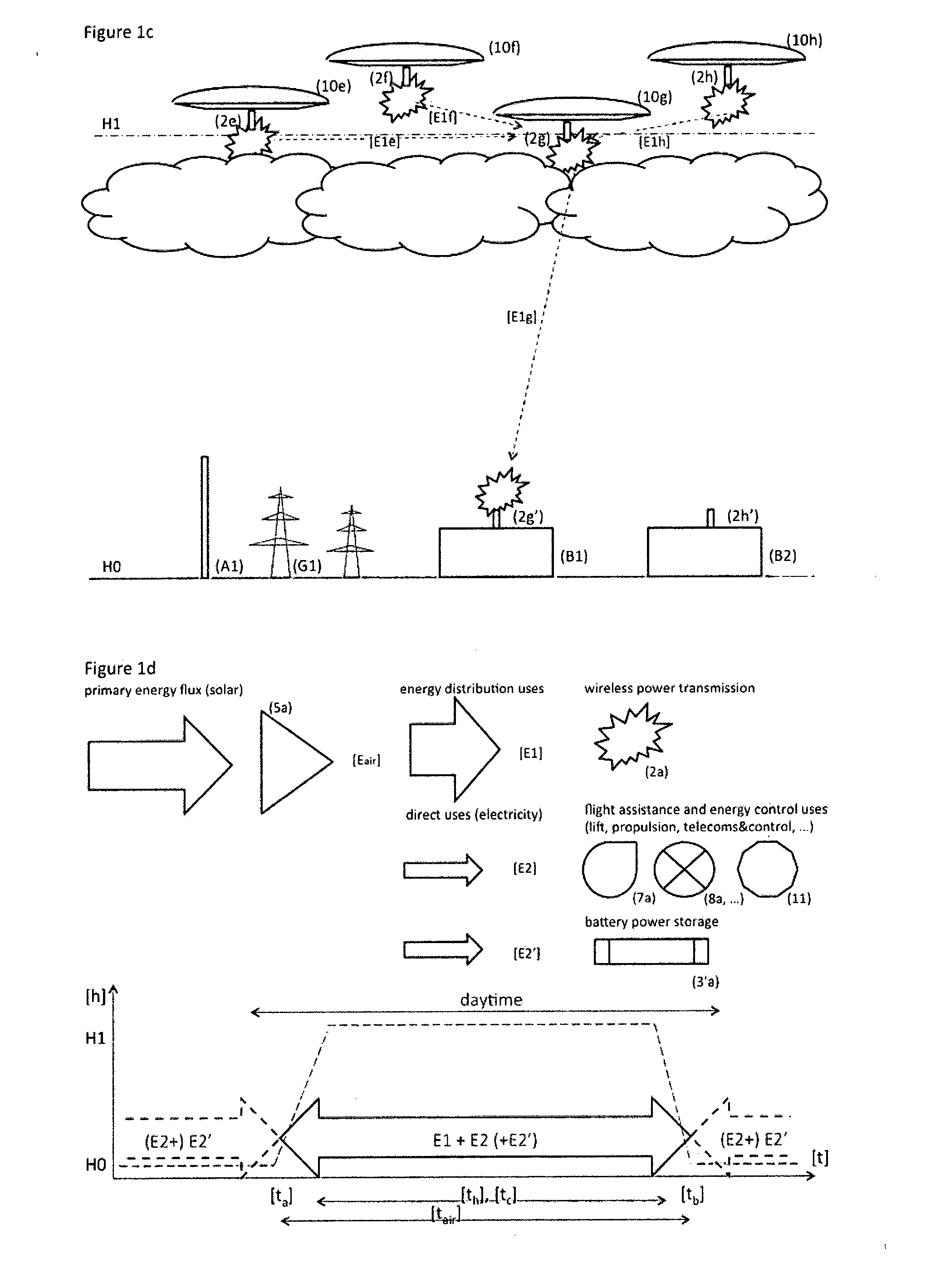
[0030]In this respect, said airships remain airborne for substantially long periods (th) mostly hovering above said destination altitude level, thereby carrying out multiple successive operations of energy generation and distribution of said energy (E1) to other airships, for the purpose of these storing energy in respective storage energy units, that continuously shuttle between the latter and respective platforms.

[0031]In another embodiment according to the invention, airships follow substantially vertical flight trajectories starting from an initial, for example ground level, thereby ascending and descending along preferentially narrow airspace volumes, at least until reaching a said altitude level, then hovering in preferentially substantially stationary geo-positions within a substantially narrow altitude range preferentially above said destination altitude level, or moving along preferentially pre-determined enclosed trajectories, preferentially within an imaginary airspace c...

second embodiment

[0084]FIGS. 2a: a process for airborne energy generation and distribution;

[0085]FIGS. 2b-2d: ground platforms for carrying out said second embodiment;

[0086]FIG. 2e: schematic diagrams of the key airborne energy processes and time evolution of basic operations of said second embodiment;

[0087]FIGS. 2f-2g: airships for carrying out said second embodiment;

third embodiment

[0088]FIGS. 3a-3b: a process for airborne energy generation and distribution;

[0089]FIGS. 3c-3d: ground platform for carrying out said third embodiment;

[0090]FIG. 3e: airship for carrying out said third embodiment;

[0091]FIG. 3f: schematic diagram of combined airship energy storage and ballast means;

[0092]FIG. 3g: schematic diagrams of the key airborne energy processes and time evolution of basic operations of said third embodiment;


PUM


Abstract

The present invention proposes a process involving the use of at least one, preferentially several non-tethered airships of at least one type, at least carrying one solar energy unit (SEU) and/or one wind energy unit (WEU) for carrying out certain airborne missions of generating a given total amount of final energy (E), whereby preferentially most of which (E1) is used for energy distribution, including airborne energy transmission by means of onboard energy transmission units (ETU), and/or storage by means of onboard, energy storage units (ESO) and supply thereof by connecting to energy devices or grids at platforms (A) or consumers (B), and whereby at least most of the remanding energy amount (E2=E−E1) is used for direct uses by said airships, such as flight assistance systems, or for other uses, such as telecommunications; The present invention also proposes distinctive features of said airships, respective platforms and energy systems associated with, different missions of airborne energy generation and distribution.

Description

CROSS-REFERENCES TO RELATED APPLICATIONS[0001]This is a U.S. national phase application of PCT / PT2011 / 000015, filed May 10, 2011, which claims priority to Portugal 105112, filed May 10, 2010, both of which are incorporated by reference in its entirety.TECHNICAL FIELD OF THE INVENTION[0002]The present invention refers to a process of using airships for energy generation and distribution. Moreover it refers to airships, respective energy systems and infrastructures for carrying out such a process.BACKGROUND OF THE INVENTION[0003]Different ways have been proposed of using airships to carry different types of wind energy devices at high altitudes, notably by means of tethered devices, in isolation (e.g., U.S. Pat. No. 4,450,364), or in tandem (e.g., U.S. Pat. No. 7,129,596 B2). The operation of tethered kites and airships constantly requires a comparatively big airspace volume, for a given energy capacity level. Moreover, depending on the actual technology and altitude range, such tethe...

Claims


Application Information

Patent Timeline
Patent Type & Authority Applications(United States)
IPC IPC(8): F03D5/00
CPCF03D9/02F03D9/021F03D9/028F03D5/00F05B2240/922Y02E10/72Y02E60/15F05B2240/92F03D9/10F03D9/11F03D9/17F03D9/18Y02E10/50Y02E10/70Y02E10/728Y02E60/16Y02E70/30F03D9/007F03D9/32H02S10/12
Inventor CARDOSO, PAULO ALEXANDRE
Owner CARDOSO PAULO ALEXANDRE
Why Eureka
Try Eureka