
Method for the automated manufacture of a fibre composite component with integrated lightning protection, and also a fibre composite component

a fiber composite and composite component technology, applied in the installation of lighting conductors, climate sustainability, sustainable transportation, etc., can solve the problems of high production cost and high level of manual work content, and achieve the effect of large width and high efficiency

Inactive Publication Date: 2013-05-16
AIRBUS OPERATIONS GMBH
View PDF2 Cites 16 Cited by
  • Summary
  • Abstract
  • Description
  • Claims
  • Application Information

AI Technical Summary

Benefits of technology

The patent text describes a method for using a same laying machine for processing both pre-preg material and lightning protection material on the same fiber composite component. The use of a narrow width of lightning protection material allows for better matching with small radii of curvature. By embedding the lightning protection material into an adhesive resin, reliable fixing of its location during the laying down process is achieved. The method also allows for easier build-up of lightning protection in regions with curved surface geometry.

Problems solved by technology

A major disadvantage of this procedure of previous known art lies in the high level of manual work content, which, among other features, leads to high production costs.

Method used


Image

  • Method for the automated manufacture of a fibre composite component with integrated lightning protection, and also a fibre composite component
  • Method for the automated manufacture of a fibre composite component with integrated lightning protection, and also a fibre composite component
  • Method for the automated manufacture of a fibre composite component with integrated lightning protection, and also a fibre composite component

Examples


Embodiment Construction

[0038]In the drawings the same design elements have the same reference numbers in each case.

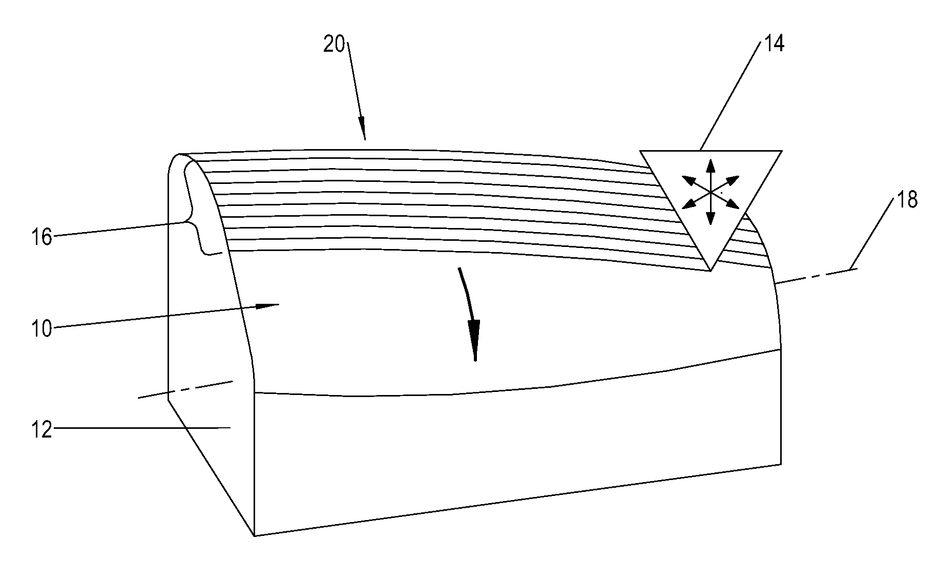
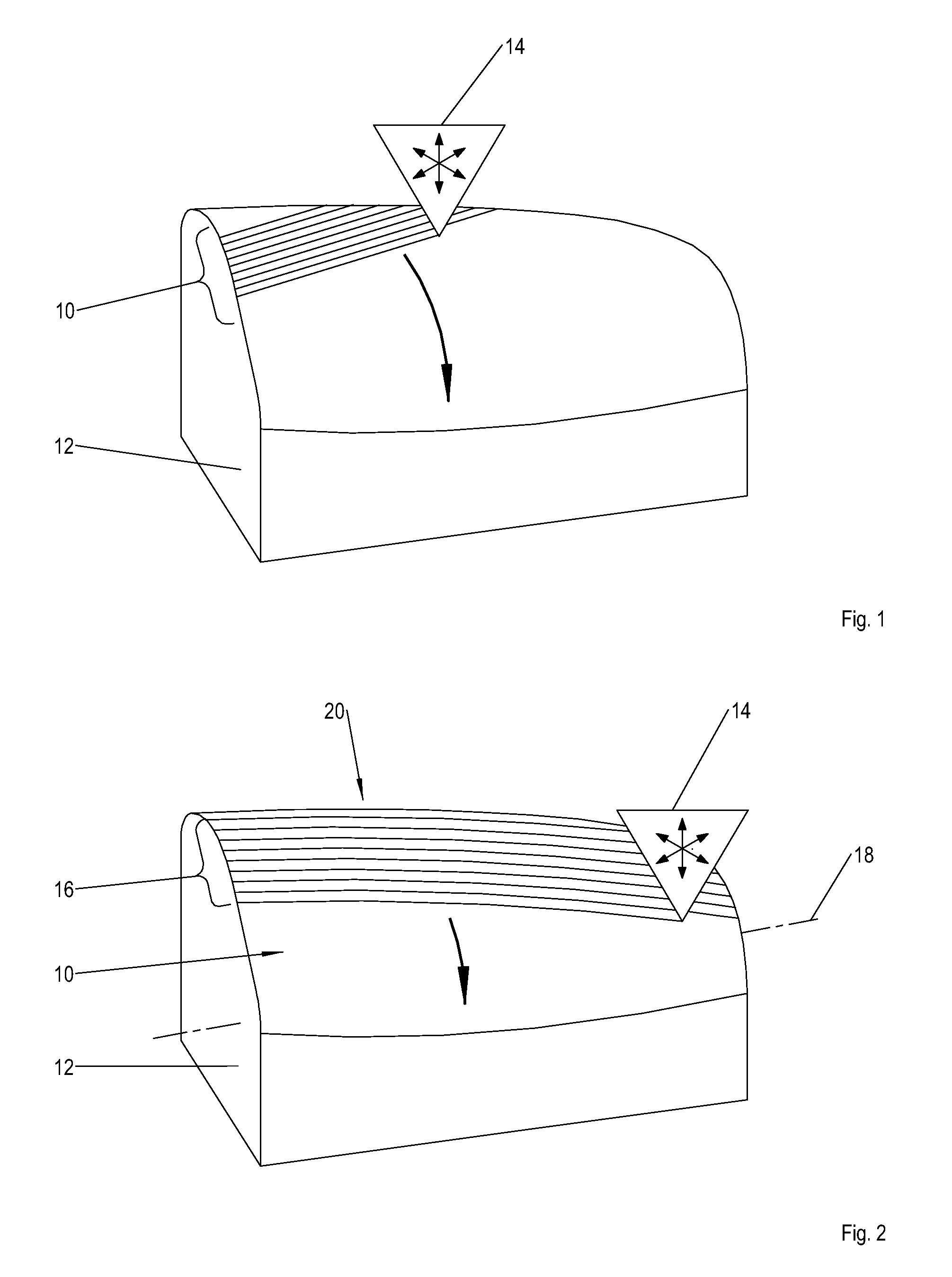
[0039]FIG. 1 illustrates in a schematic representation the laying down of a ribbon-form pre-preg material on a positive mold in the course of the first variant of the method, Here both a ribbon-form pre-preg material and also dry, non-impregnated, ribbon-form reinforcing fiber strands can be used. The method is described under the premise of the deployment of a ribbon-form pre-preg material.

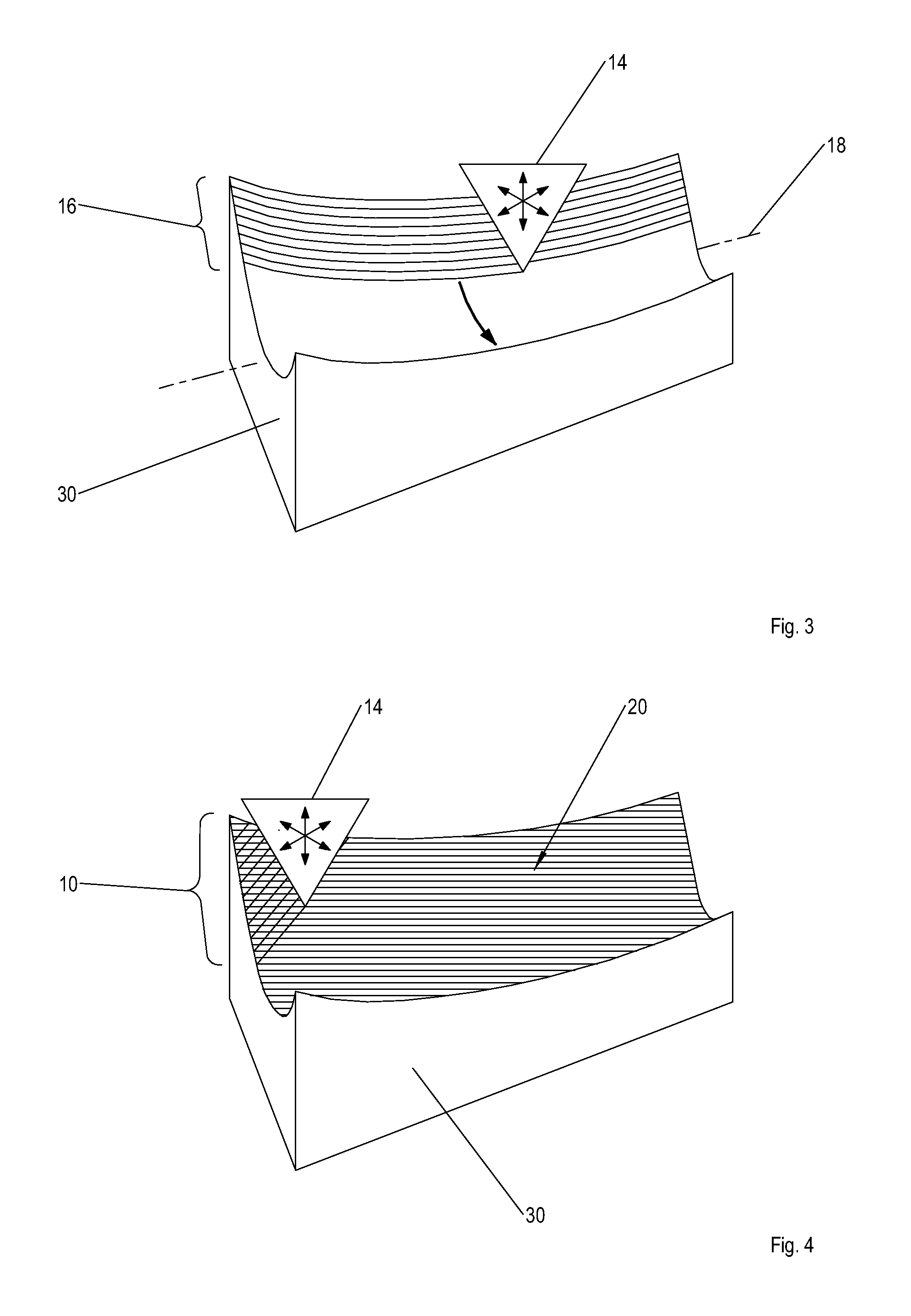
[0040]In accordance with the first variant of the method, in step a) of the method a ribbon-form pre-preg material 10 is preferably firstly laid down successively—e.g., in the direction of the undesignated black arrow, represented with a thick line—on a positive mold 12 by means of an automated laying machine 14, not represented in any further detail, until the prescribed material thickness and geometry of the later fiber composite component are achieved. The positive mold 12 defines the later geometrical ...


PUM

PropertyMeasurementUnit
Widthaaaaaaaaaa
Widthaaaaaaaaaa
Thicknessaaaaaaaaaa

Abstract

A method for manufacturing a fiber composite plastic component with integrated lightning protection. The steps include, for a positive mold, automatically laying down a ribbon-form pre-preg material or dry ribbon-form reinforcing fiber strands onto the mold. Then, automatically laying down a ribbon-form lightning protection material onto the pre-preg material or the reinforcing fiber strands. For a negative mold, the steps include automatically laying down the lightning protection material on the negative mold, then automatically laying down the pre-preg material or the dry reinforcing fiber strands onto the positioned lightning protection material. The method also includes curing the laminate construction formed with the pre-preg material and the lightning protection material to form the fiber composite component, or infiltrating the dry reinforcing fiber strands with a plastic, and subsequently curing the laminate construction formed with the infiltrated reinforcing fiber strands and the lightning protection material to form the fiber composite component.

Description

BACKGROUND OF THE INVENTION[0001]The invention concerns a method for the automated manufacture of a fiber composite component, in particular a shell module of an aircraft, with integrated lightning protection, wherein the fiber composite component is formed with a fiber composite plastic, in particular with a thermosetting fiber composite plastic.[0002]In modern aircraft construction components that are manufactured with fiber-composite plastics are widely deployed. In the structural regions of aviation vehicles carbon fiber-reinforced thermosetting plastics are primarily deployed, wherein carbon fiber-reinforced thermoplastic high-performance plastics are also encountered to some extent. Furthermore other reinforcing fibers, such as, for example, glass fibers, Kevlar® fibers, or Aramid® fibers, can be deployed. With the deployment of fiber composite plastics a considerable potential for weight saving ensues; among other factors this leads to increased ranges by virtue of reduced fu...

Claims


Application Information

Patent Timeline
IPC IPC(8): H02G13/00B29C70/88
CPCH02G13/00B29C70/88Y02T50/433B29C70/882B29C70/386Y02T50/40
Inventor DE JONG, CLAASKASTE, MICHAELFASTERT, CLAUSFIDEU, PAULINSEEGEL, HAUKE
Owner AIRBUS OPERATIONS GMBH
Learn More