
Wireless charging system and method

a charging system and wireless charging technology, applied in the field of wireless chargers, can solve the problems of invalid magnetic field not only wasting energy but also wasting energy

Inactive Publication Date: 2013-05-16
ACER INC
View PDF3 Cites 45 Cited by
  • Summary
  • Abstract
  • Description
  • Claims
  • Application Information

AI Technical Summary

Benefits of technology

This patent describes various embodiments of wireless charging systems and methods that use sensing devices, charging coil arrays, and processors to determine the shape of the recharging area of an electronic device and selectively turn on a part of the charging coil array to charge the device by wireless charging. The technical effects of these embodiments include improved charging efficiency and accuracy, as well as enhanced user experience.

Problems solved by technology

If a plurality of devices need to charge at the same time, the traditional cable-configuration chargers will become difficult to use.
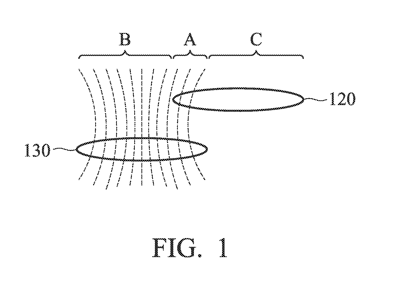
Therefore, the receiving antenna 120 is only influenced by the magnetic field from transmitting antenna in the area A, and the electronic device cannot be fully effectively charged.
The invalid magnetic field is not only wasting energy but also jeopardizing the health of users.
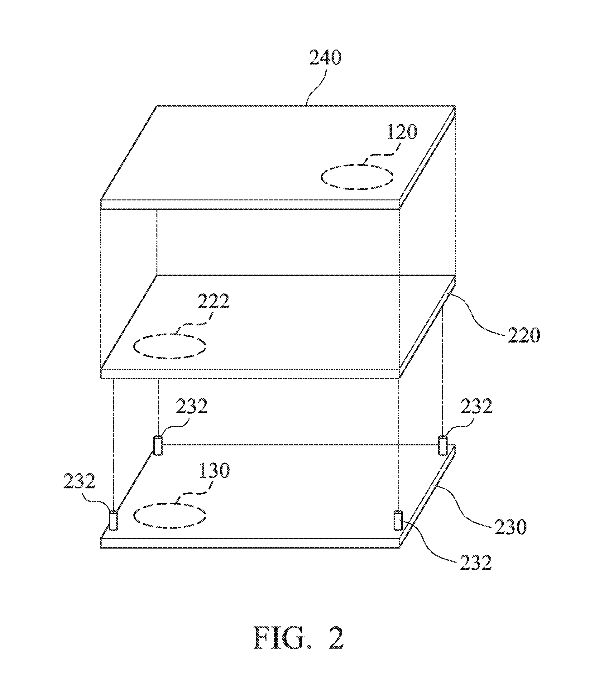
Therefore, the prior solution cannot fully effectively charge the electronic device 240 and avoid endangering the user's health.
Therefore, the wireless charger 230 does not provide economic benefits and meet user needs.
Furthermore, the inappropriate use of the wireless charger 230 may put the user's physical health at risk.

Method used


Image

  • Wireless charging system and method
  • Wireless charging system and method
  • Wireless charging system and method

Examples


Embodiment Construction

[0024]The following description is of the best-contemplated mode of carrying out the invention. This description is made for the purpose of illustrating the general principles of the invention and should not be taken in a limiting sense. The scope of the invention is best determined by reference to the appended claims.

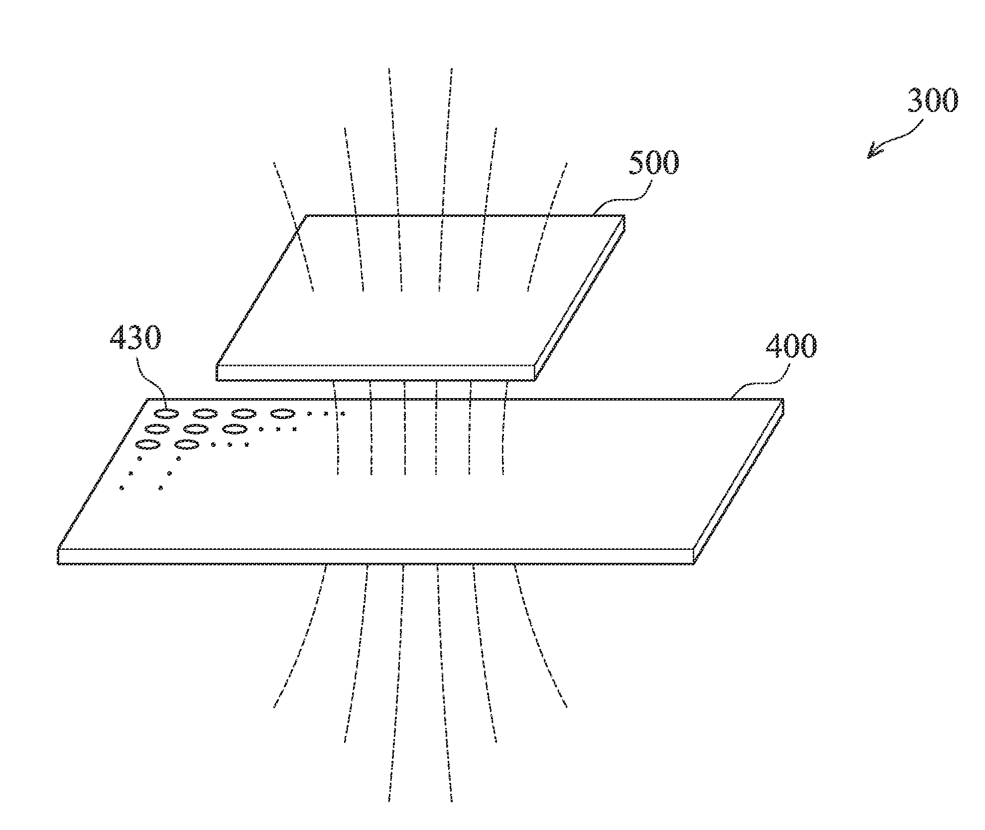
[0025]As shown in the FIG. 3, the present invention discloses a schematic diagram of a wireless charging system. The wireless charging system 300 includes a wireless charger 400 and an electronic device 500, wherein the electronic device 500 includes a charging coil array 430. The wireless charger 400 determines the shape of the recharging area of the electronic device 500 when the electronic device 500 is placed on (or near) the top of the wireless charger 400. The wireless charger 400 turns on a part of the charging coil array 430 corresponding to the shape of recharging area. After being conducted, the coils which are part of the charging coil array 430 induce a mag...


PUM


Abstract

The present invention provides a wireless charger including a sensing device, a charging coil array and a processor. The sensing device determines the shape of the recharging area of an electronic device placed on the wireless charger. The charging coil array includes a plurality of dynamic charging coils and selectively turns on a part of the dynamic charging coils. The processor drives the part of the dynamic charging coils to charge the electronic device by wireless charging, wherein the part of the dynamic charging coils of the charging coil array is corresponding to the shape of the recharging area.

Description

CROSS REFERENCE TO RELATED APPLICATIONS[0001]This Application claims priority of Taiwan Patent Application No. 100141016, filed on Nov. 10, 2011, the entirety of which is incorporated by reference herein.BACKGROUND OF THE INVENTION[0002]1. Field of the Invention[0003]The present invention relates to a wireless charger, and in particular relates to a wireless charger executing a wireless charging of an electronic device according to the shape of the electronic device.[0004]2. Description of the Related Art[0005]Generally, battery-powered devices (such as wireless electronic devices) need a matched adapter which usually is an AC power cord. If a plurality of devices need to charge at the same time, the traditional cable-configuration chargers will become difficult to use.[0006]Another method of charging battery-powered device is wireless energy transmission technology. The wireless energy transmission technology is based on the inductive coupling and the electromagnetic sensing betwee...

Claims


Application Information

Patent Timeline
IPC IPC(8): H02J7/00
CPCH02J7/025H02J50/402H02J50/90H02J50/10H02J7/00034H02J50/80H02J7/00
Inventor LIN, YUNG-SEN
Owner ACER INC
Learn More