
LED lighting device and cable connection detection device

a detection device and lighting device technology, applied in the direction of coupling device connection, optics, instruments, etc., can solve the problems of cable connection errors in the assembly process, and achieve the effects of improving the accuracy of detecting the connection state of the ffc, more reliably detected, and improving usability, workability, or the lik

Inactive Publication Date: 2013-05-16
FUNAI ELECTRIC CO LTD
View PDF3 Cites 10 Cited by
  • Summary
  • Abstract
  • Description
  • Claims
  • Application Information

AI Technical Summary

Benefits of technology

The present invention provides an LED lighting device that can reliably detect abnormal connections, such as reverse or oblique insertion of cables, to prevent malfunctions or improve usability and maintainability. The invention can also accurately detect the connection state of the flexible flat cable (FFC) even when it is obliquely inserted, which can improve accuracy and reduce costs. However, the invention can also detect the abnormal connection of the FFC when it is fully connected.

Problems solved by technology

In a product having a connection by a cable such as the FFC, cable connection errors can be occurred in an assembling process.

Method used


Image

  • LED lighting device and cable connection detection device
  • LED lighting device and cable connection detection device
  • LED lighting device and cable connection detection device

Examples


Embodiment Construction

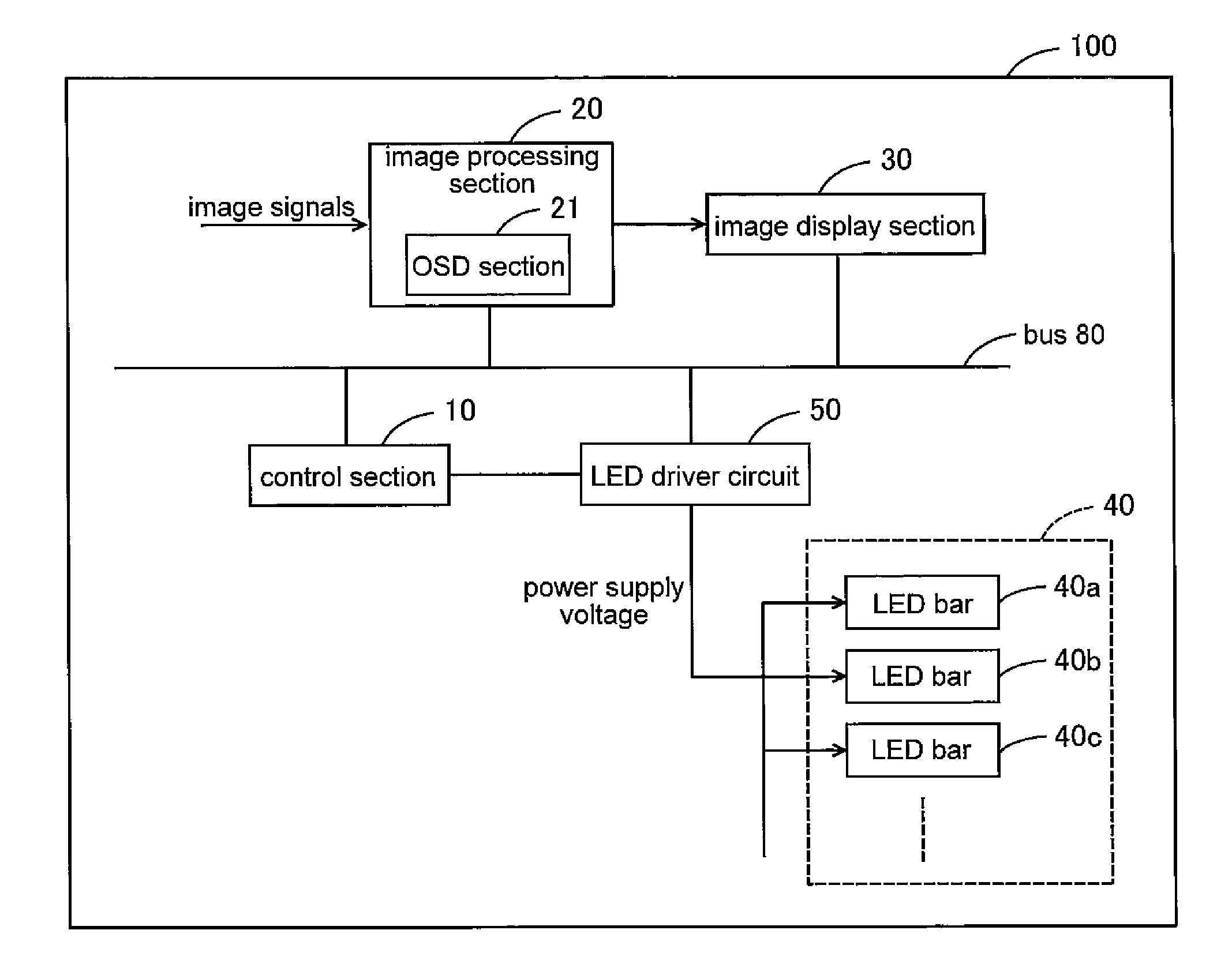
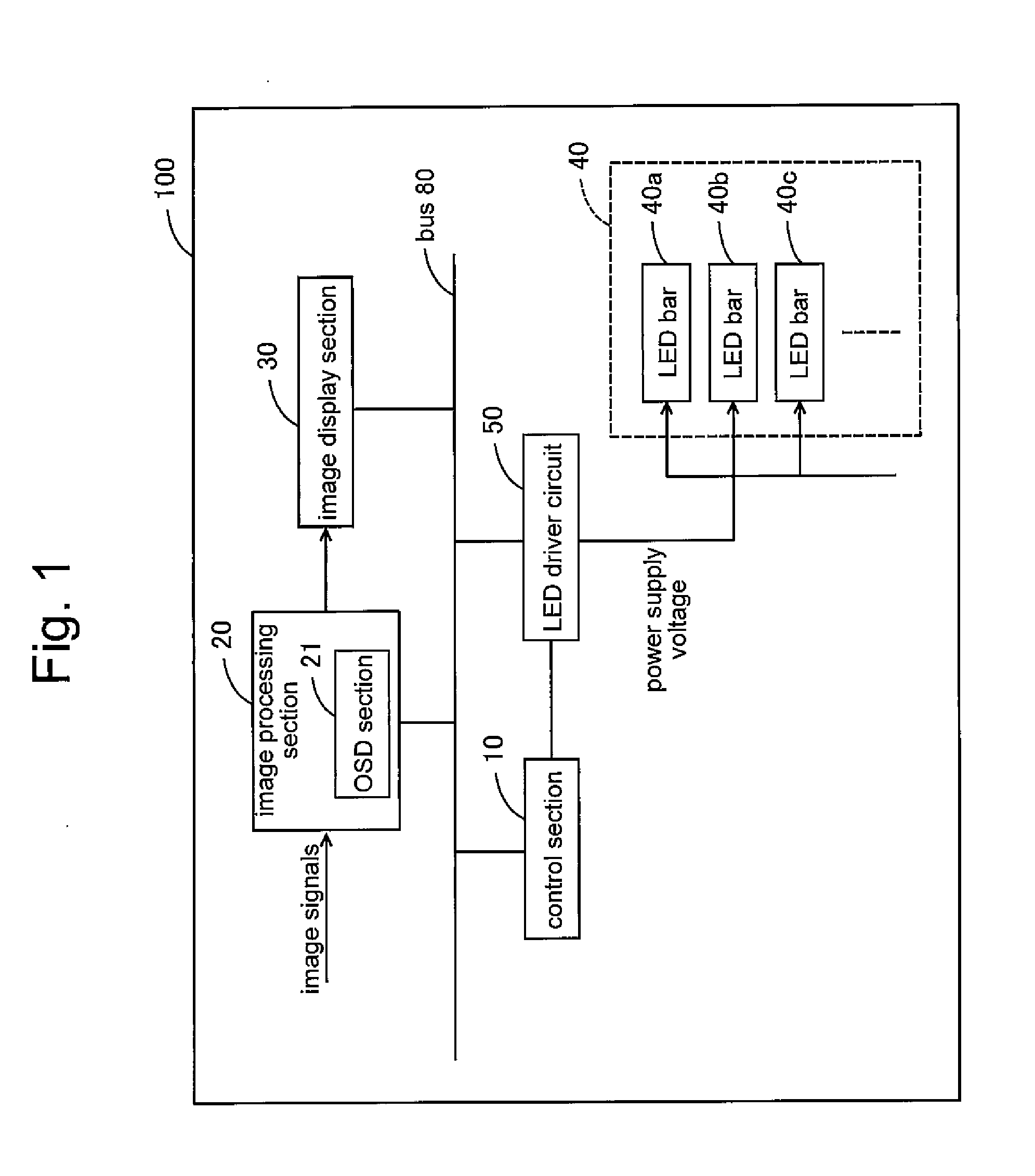
[0036]Hereinafter, embodiments of the present invention will be explained with reference to FIGS. 1 to 8.

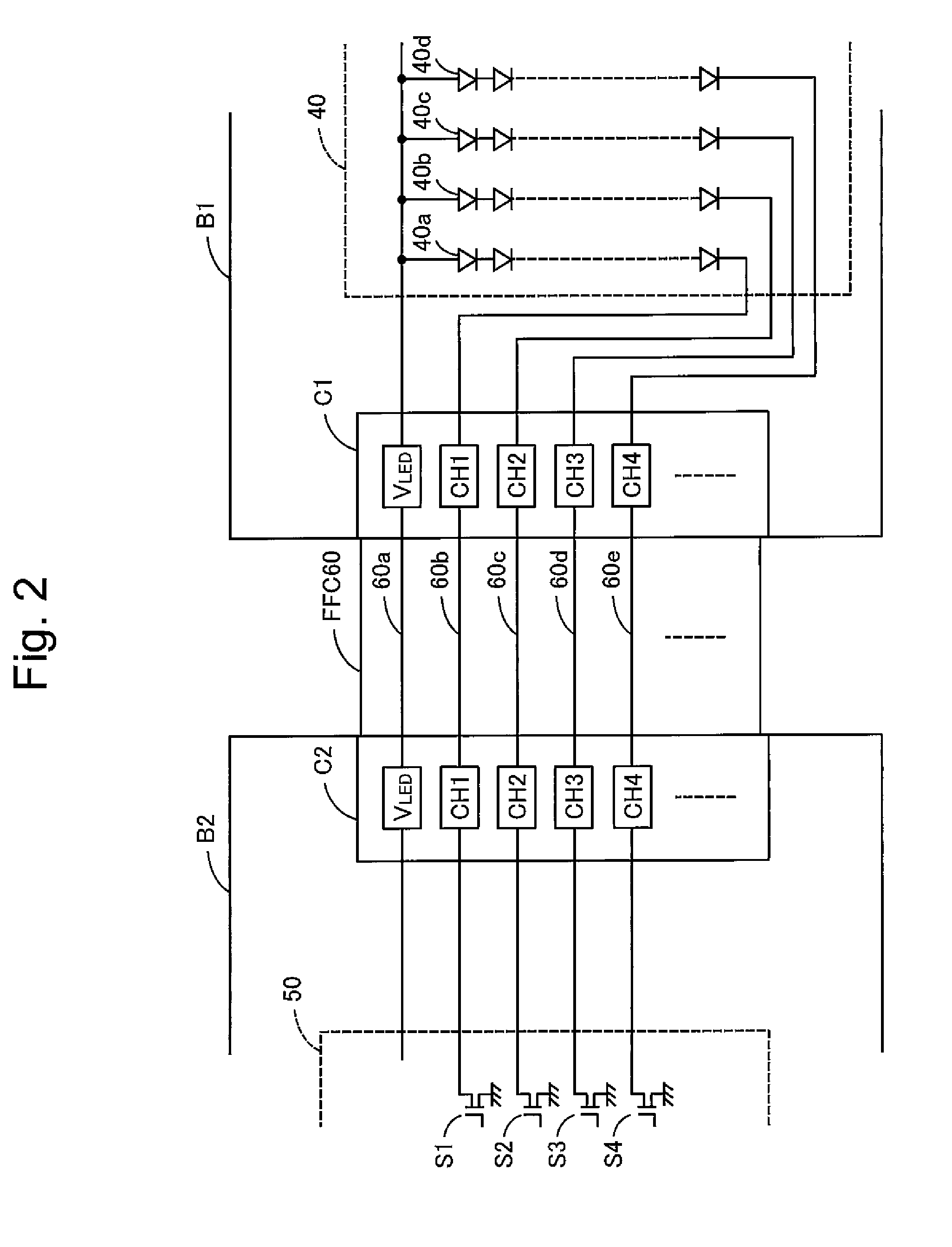
[0037]In an LED lighting device, an LED board B1 mounting LEDs is connected to an LED driver board B2 that forms an LED driver circuit 50 to turn on the LEDs by an FFC 60 having plural transmission lines. Consequently, the LED driver circuit 50 turns on the LEDs via the FFC 60. The LED lighting device is configured to have a voltage dividing resistor and a connection detection section. The voltage dividing resistor is composed of a first resistor 71a and a second resistor 71b that are mounted on the LED board B1. The connection detection section is connected to one end of the voltage dividing resistor via a first transmission line 73 of the FFC 60, connected to another end of the voltage dividing resistor via the second transmission line 75 of the FFC 60, and connected to the dividing point of the voltage dividing resistor via a third transmission line 74 of the FFC 60.

[0038]In t...


PUM


Abstract

To reliably detecting cable connection errors such as a reverse insertion or an oblique insertion of a cable, an LED board and an LED driver circuit board are connected by an FFC, a voltage dividing resistor is mounted on the LED board. A connection detection section is connected to one end of the voltage dividing resistor via a first transmission line of the FFC, connected to another end of the voltage dividing resistor via a transmission line of the FFC, and connected to the dividing point of the voltage dividing resistor via a third transmission line of the FFC. At least the third transmission line is configured not to pass through a center of the FFC, or the resistance values of the resistor and the resistor are different. A connection state of the FFC based on a voltage of the dividing point is detected via the third transmission line.

Description

TECHNICAL FIELD[0001]The present invention relates to an LED (Light-Emitting diode) lighting device in which an LED board and an LED driver board are connected by an FFC (Flexible Flat Cable), and a cable connection detection device in which a first board and a second board are electrically connected by the FFC (Flexible Flat Cable).BACKGROUND ART[0002]In a product having a connection by a cable such as the FFC, cable connection errors can be occurred in an assembling process. The following technologies are disclosed for detecting the cable connection errors.[0003]Japanese Patent Application Publication 2008-304363 discloses a cable connection detection device in which a loop circuit is formed from a connector to attach one terminal of an FFC and back to the one terminal via another connector to attach another terminal.[0004]Japanese Patent Application Publication S64-2271 discloses a cable connection monitoring circuit that has a cable formed by aligning plural transmission lines i...

Claims


Application Information

Patent Timeline
IPC IPC(8): G01R31/04G02F1/1335H05B37/00
CPCG01R31/041H01R12/77H05B37/00H01R13/7175G02F1/1336H01R13/641G01R31/67
Inventor TSUJII, TAKAYUKI
Owner FUNAI ELECTRIC CO LTD
Learn More