Printing system, control method, and computer-readable medium

Inactive Publication Date: 2013-05-16
CANON KK
View PDF14 Cites 21 Cited by
  • Summary
  • Abstract
  • Description
  • Claims
  • Application Information

AI Technical Summary

Benefits of technology

[0008]The present invention provides a mechanism capable of properly performing print cancel processing even when a prin

Problems solved by technology

Conventionally, it is difficult to instruct a change of print settings when the user issues a print request to a printing apparatus for print data temporarily stored in a server.
If this printer driver is applied to the server of the pull print system, the number of PDL jobs to be generated from one print data

Method used


Image

  • Printing system, control method, and computer-readable medium
  • Printing system, control method, and computer-readable medium
  • Printing system, control method, and computer-readable medium

Examples


first embodiment

[0036][System Arrangement]

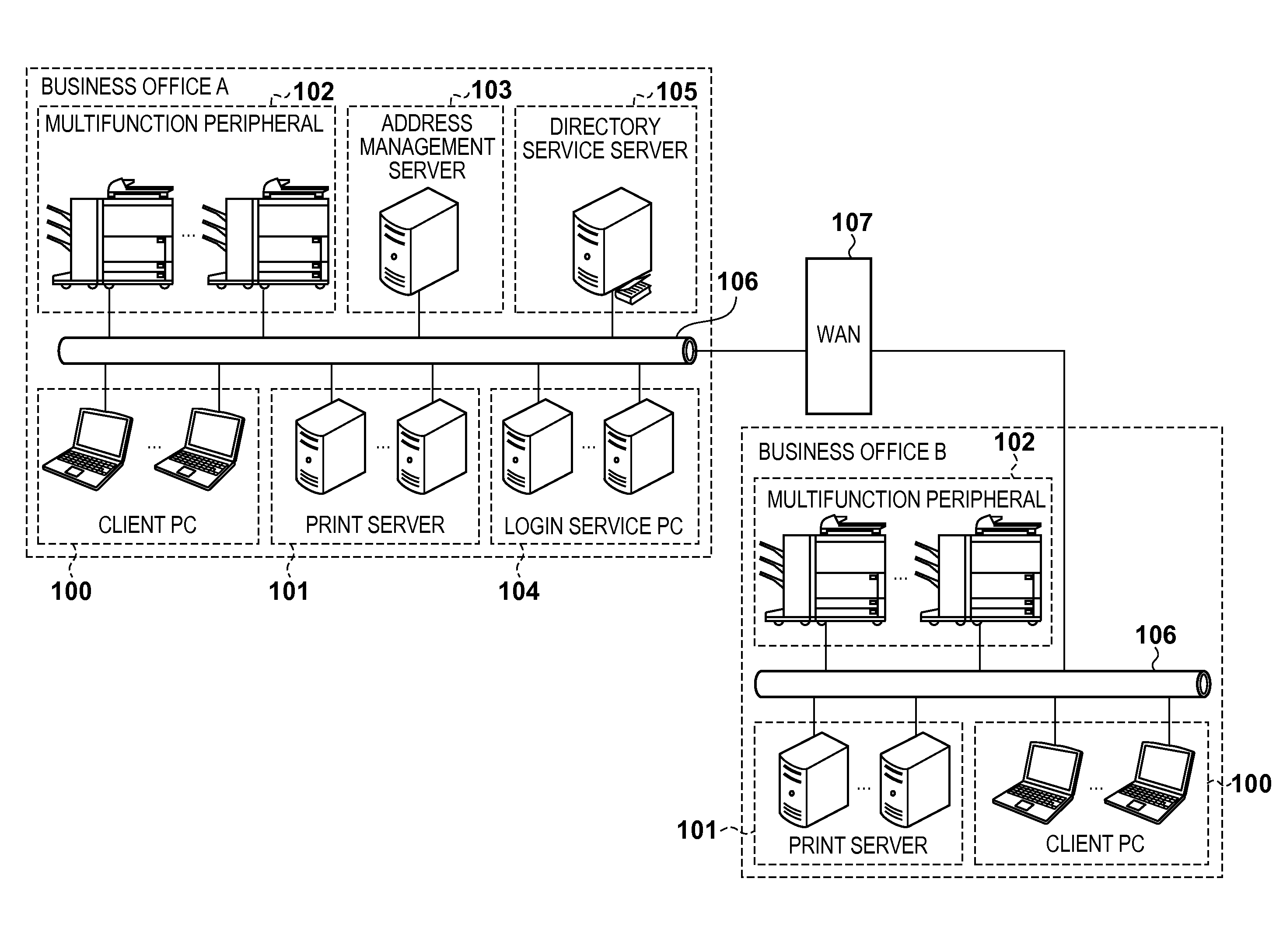
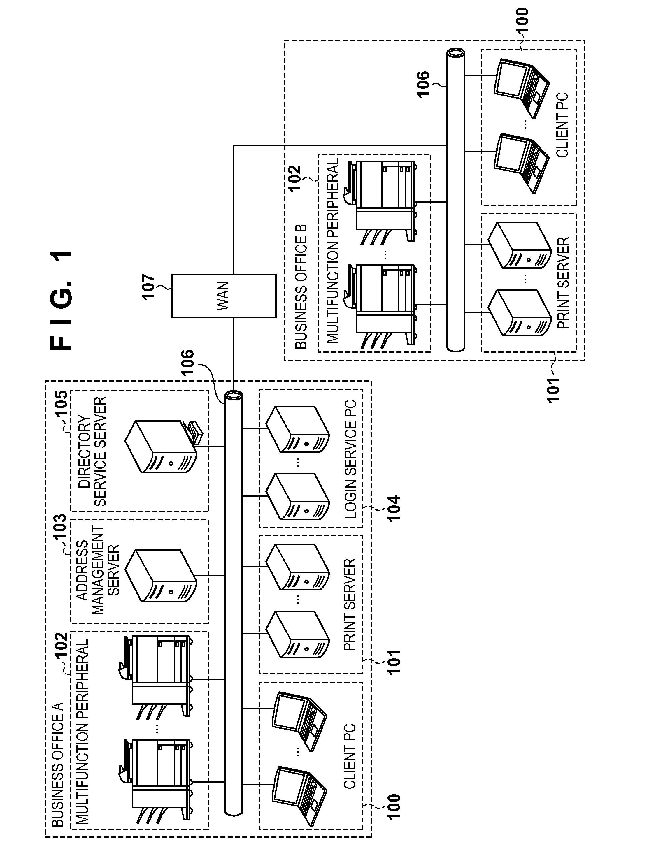
[0037]FIG. 1 is a view exemplifying the arrangement of a printing system to which the present invention is applicable. “Business office A” shown in FIG. 1 includes one or a plurality of client PCs 100, one or a plurality of print servers 101, one or a plurality of multifunction peripherals 102, an address management server 103, one or a plurality of login service PCs 104, and a directory service server 105. These apparatuses are connected via a local area network (LAN) 106. A plurality of apparatuses of the same type may be, for example, installed for respective users or arranged on respective floors.

[0038]A virtual printer driver is installed in the client PC 100. The virtual printer driver generates a print job of an intermediate format independent of a specific multifunction peripheral based on data received from a client application, and transmits it to the print server 101. Note that a print job of an intermediate format indicates print data of a forma...

second embodiment

[0137]The second embodiment for practicing the present invention will be described with reference to the accompanying drawings. In the first embodiment, the client PC 100 and print server 101 exist as separate apparatuses. To the contrary, in the second embodiment, a client PC 100 implements the function of a print server 101. Although the overall pull print sequence in the printing system according to the first embodiment is shown in FIGS. 4 and 12, an overall pull print sequence according to the second embodiment is shown in FIGS. 18 and 19.

[0138]In FIGS. 18 and 19, the print server 101 does not exist, and the client PC 100 implements a function equivalent to the print server 101. This system does not require the print server 101. However, the arrangement in the second embodiment causes a new problem specific to this arrangement. More specifically, in 3-4 of FIG. 19, a printer driver 408 outputs a plurality of PDL jobs and an End job. As described in the first embodiment, the prin...


PUM


Abstract

A system comprises an image forming apparatus and a server, the image forming apparatus including: a receiving unit which receives the series of data from the server; a transfer unit which transfers a plurality of print jobs included in the series of data to a printing unit; and an accepting unit which accepts a cancel instruction for the series of data from a user, wherein when the receiving unit accepts the cancel instruction while receiving the series of data, the receiving unit discards the plurality of print jobs until termination data is received, and when the transfer unit accepts the cancel instruction while transferring the series of data, the transfer unit cancels transfer of the plurality of print jobs to the printing unit, and instructs the printing unit to cancel printing of a transferred print job.

Description

BACKGROUND OF THE INVENTION[0001]1. Field of the Invention[0002]The present invention relates to a printing system, control method, and computer-readable medium. Particularly, the present invention relates to a technique when an image forming apparatus controls printing of data stored in a print server.[0003]2. Description of the Related Art[0004]There has conventionally been proposed a so-called “pull print” printing system capable of outputting print data from a printing apparatus in response to a print request from a user to the printing apparatus for print data temporarily stored in a server (see, for example, Japanese Patent No. 4033857). This printing system allows the user to output print data not to a specific printing apparatus but from a printing apparatus of his choice in accordance with a print request in printing from an application.[0005]Conventionally, it is difficult to instruct a change of print settings when the user issues a print request to a printing apparatus f...

Claims


Application Information

Patent Timeline
IPC IPC(8): G06K15/02
CPCH04N2201/3273G06F3/1288H04N1/00233H04N1/00411H04N1/00477H04N1/00912H04N1/32635H04N1/32657H04N2201/0098H04N2201/0094H04N2201/3214H04N2201/3222H04N2201/3216H04N2201/3226G06F3/1203G06F3/1238G06F3/1241G06F3/1258G06F3/1267G06F3/1274H04N1/0023
Inventor TAKAGI, YOSHIHIRO
Owner CANON KK
Why Eureka
Try Eureka