Method for manufacturing wire, apparatus for manufacturing wire, and copper alloy wire

a manufacturing apparatus and technology for copper alloy wire, applied in heat treatment apparatus, furnaces, conductors, etc., can solve the problems of high equipment cost, inability to perform the age-treatment of the usual precipitation-type alloy, etc., to achieve the effect of reducing the number of processes

Inactive Publication Date: 2009-09-17
FURUKAWA ELECTRIC CO LTD
View PDF2 Cites 15 Cited by
  • Summary
  • Abstract
  • Description
  • Claims
  • Application Information

AI Technical Summary

Benefits of technology

[0064]According to the method for manufacturing wire of the invention, it is possible to carry out aging heat treatment by continuous annealing. Furthermore, since the annealing while running equipment can be installed in tandem with various continuous equipment (for example, wire twisting equipment, covering equipment, drawing equipment), the number of the processes can be reduced.
[0065]In addition, when a current applying equipment for exclusively solution purpose is connected in tandem at upstream side of the annealing while ru

Problems solved by technology

Such a short time makes it impossible to perform the age-treatment of the usual precipitation-type alloy.
Further, higher cost is needed for the equipment in the above described batch-type annealing furnace, or the continuous batch-type annealing furnace, and vast space is needed for installing the furnace.
In addition, the furnace may not be installed in tandem with a wir

Method used


Image

  • Method for manufacturing wire, apparatus for manufacturing wire, and copper alloy wire
  • Method for manufacturing wire, apparatus for manufacturing wire, and copper alloy wire
  • Method for manufacturing wire, apparatus for manufacturing wire, and copper alloy wire

Examples


example 1

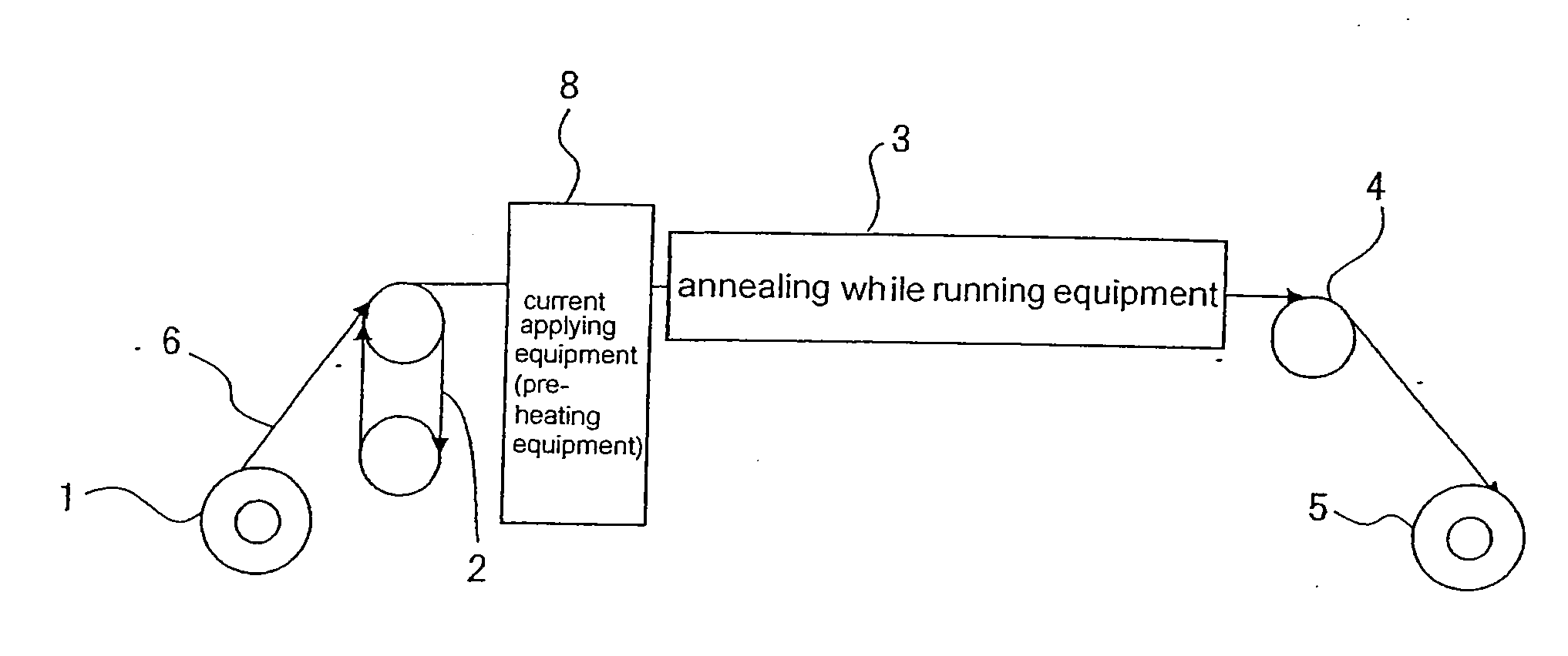
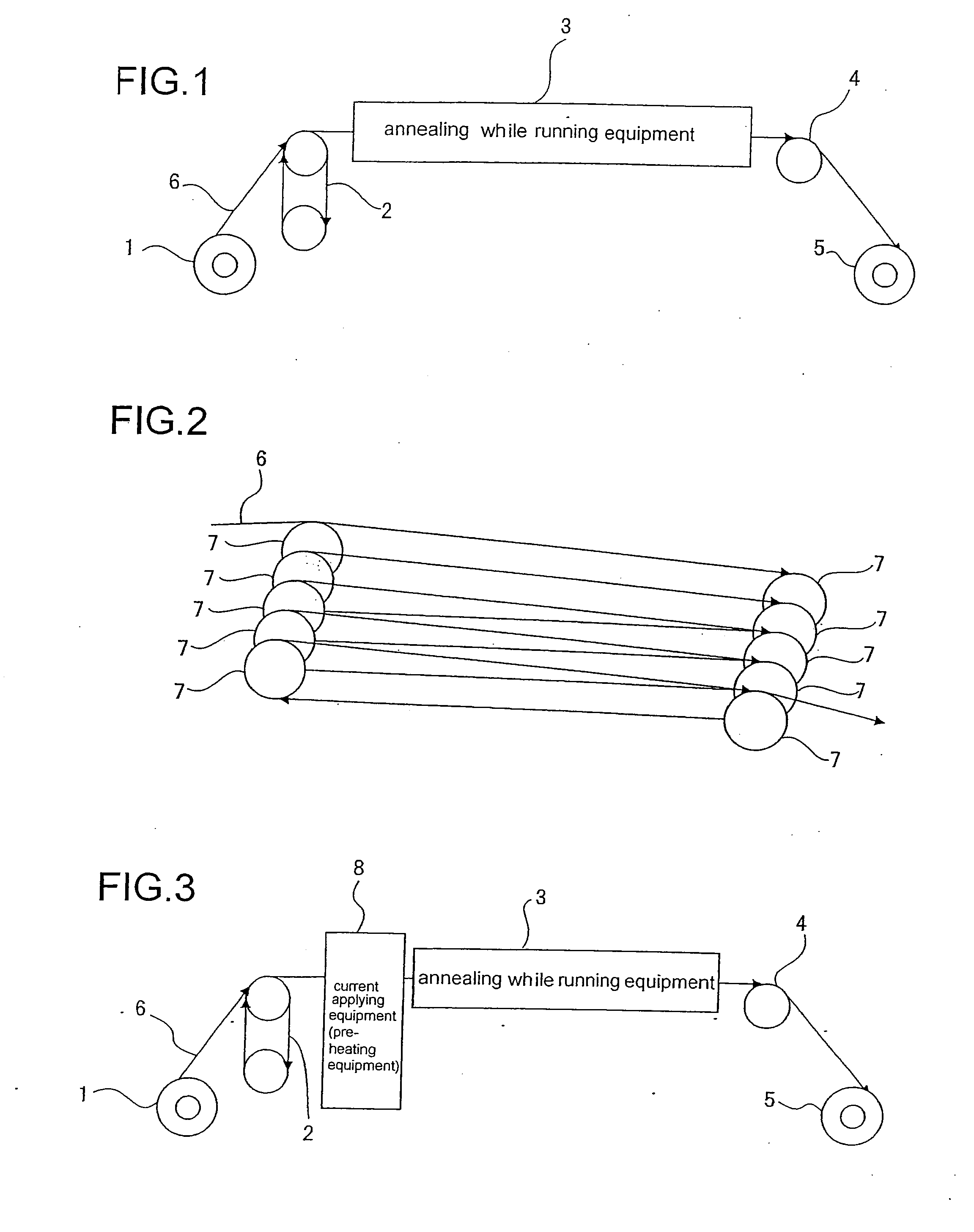
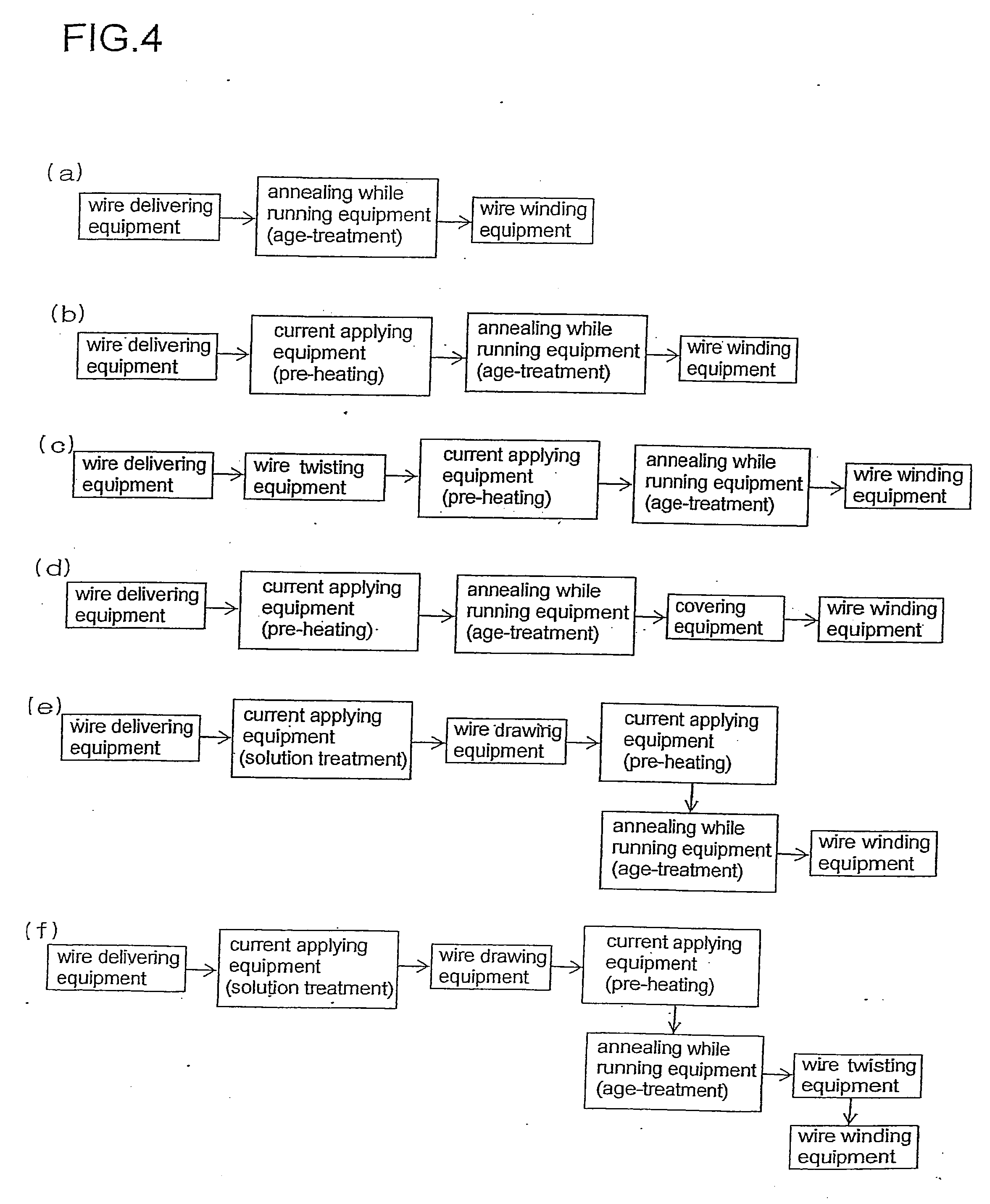
[0197]The alloys Nos. 1 to 38 are subjected to the solution treatment, and then the copper alloy wires having the diameter of 0.1 mm are formed. The copper alloy wires are continuously age-treated under the conditions as shown in Table 2 using the apparatus for manufacturing wire as depicted in FIGS. 3 and 4(b). The results are shown in Table 2. For comparison, the copper alloy wires having the diameter of 0.1 are formed using the above described alloys. The copper alloy wires are age-treated by the conventional method using the batch furnace. More specifically, the wires are heated to the temperature (degrees Celsius) as shown in Table 2, and held at the temperature for a time period of heating time (sec), and then wound by the wire winding equipment. The tensile strength (MPa) and electrical conductivity (% IACS) of the wire in the annealing while running equipment are shown in Table 2.

TABLE 2HeatingTensileElectricalAdhesionSampleAlloytimestrengthdonductivityafterNo.No.Temperature...

example 2

[0199]The example with the diameter of the copper alloy wire varied is shown. More specifically, alloy Nos. 16 and 22 as shown in Table 1 are subjected to solution treatment, and then the copper alloy wires having the diameters of 0.03 mm, 0.01 mm, 0.9 mm, 3 mm are formed, respectively. The copper alloy wires are continuously age-treated under the conditions as shown in Table 3 using the apparatus for manufacturing wire as depicted in FIGS. 3 and 4(b).

TABLE 3HeatingTensileElectricalAdhesionSampleAlloyDiametertimestrengthconductivityafterNo.No.(ø mm)Temperature(sec)(MPa)(% IACS)aging51160.0348090063944None52160.150090064545None53160.950090063444None54163.050090062144None55220.0345090050273None56220.147090050573None57220.947090049873None58223.047090048372None

[0200]As is clear from Table 3, all the samples Nos. 51 to 58 (i.e., Cu—Ni—Si alloys No. 16, Cu—Cr alloys No. 22) are subjected to necessary age-treatment without adhesion after age-treatment. More specifically, it is appreciated ...

example 3

[0201]The same tests as Example 1 are carried out using the apparatus for manufacturing wire as shown in FIGS. 5, 6, and 8(a) in which the wire is heated by applying current while running for age-treatment. The center values of the temperatures of the age-treatment are respectively set to be the temperature as shown in Table 2 in Example 1. The difference between the maximum temperature and the minimum temperature is set to be 40 degrees. For example, the temperature of 500 degrees Celsius in Table 2 means that the center value of the temperature is set to be 500 degrees Celsius, the maximum temperature is set to be 520 degrees Celsius, and the minimum temperature is set to be 480 degrees Celsius.

[0202]As a result, the samples of the present Example which correspond to the samples Nos. 1 to 38 in Table 2 of Example 1 show the same result as those of the samples in Examples 1 in connection with the tensile strength (MPa) and electrical conductivity (% IACS) of the wire in the anneali...


PUM

PropertyMeasurementUnit
Temperatureaaaaaaaaaa

Abstract

An apparatus for manufacturing wire comprising: a wire delivering equipment, a wire winding equipment, and an annealing while running equipment installed between the wire delivering equipment and the wire winding equipment, the age-precipitation copper alloy wire being passed in such manner that the wire turns around a plurality of times along a running route in the annealing while running equipment. The current applying equipment to raise a temperature of the age-precipitation copper alloy wire by generated Joule heat may be installed at upstream side of the annealing while running equipment. Another current applying equipment for solution treatment may be installed in tandem at upstream side of the annealing while running equipment. In place of the annealing while running equipment, a current applying equipment may be connected in tandem for age-treatment. By using those equipments, age-precipitation copper alloy wire having the diameter of from 0.03 mm to 3 mm may be obtained.

Description

FIELD OF THE INVENTION[0001]The present invention relates to a method for manufacturing wire, an apparatus for manufacturing wire, and copper alloy wire, the wire of which is used for a wiring material applied to an automobile and robot, a lead wire applied to electronic devices, a connector pin, coil spring or the like.BACKGROUND OF THE INVENTION[0002]As a wiring material applied to an automobile, there has been used an electrical wire in which a conductor made of a twisted wire of soft copper wire is concentrically covered by an insulator. In this field, the amount of the electric wire is increased to satisfy various desired high level functions of the automobile, thus the weight of the electric wire increases. On the other hand, a lighter body of the vehicle is desired, and thinner diameter as well as higher strength of the wire conductor is desired and required.[0003]Precipitation-type alloy wire may be listed as the wire conductor having excellent mechanical and electrical prop...

Claims


Application Information

Patent Timeline
IPC IPC(8): C21D9/62C22F1/08C22C9/00C22C9/06C22C9/02C22C9/04
CPCC22C9/00C22C9/06C22F1/00C22F1/08H01B1/026H01B13/0016C21D9/62C21D1/40H01B13/0006H01B13/00
Inventor TAKAHASHI, ISAOKITAZATO, KEISUKE
Owner FURUKAWA ELECTRIC CO LTD
Why Eureka
Try Eureka