Lithium Battery and Manufacturing Method Thereof

a technology of lithium battery and manufacturing method, which is applied in the field of lithium battery, can solve the problems of reducing battery life, reducing battery life, and high cost of providing safety measures, and achieves the effects of low cost, reduced number of processes, and reduced internal resistan

Inactive Publication Date: 2008-06-19
KYOTO UNIV
View PDF7 Cites 37 Cited by
  • Summary
  • Abstract
  • Description
  • Claims
  • Application Information

AI Technical Summary

Benefits of technology

[0010]The number of process is reduced and internal resistance is also small and therefore a battery with low cost and high output can be obtained and expansion of application field can be expected.

Problems solved by technology

As a result, battery performance lowers to reduce battery life.
Furthermore, the aforementioned organic solvent is inflammable and therefore it is very expensive in providing measures for safety.

Method used


Image

  • Lithium Battery and Manufacturing Method Thereof
  • Lithium Battery and Manufacturing Method Thereof
  • Lithium Battery and Manufacturing Method Thereof

Examples


example

Examples 1 to 3 and Comparative Example 1

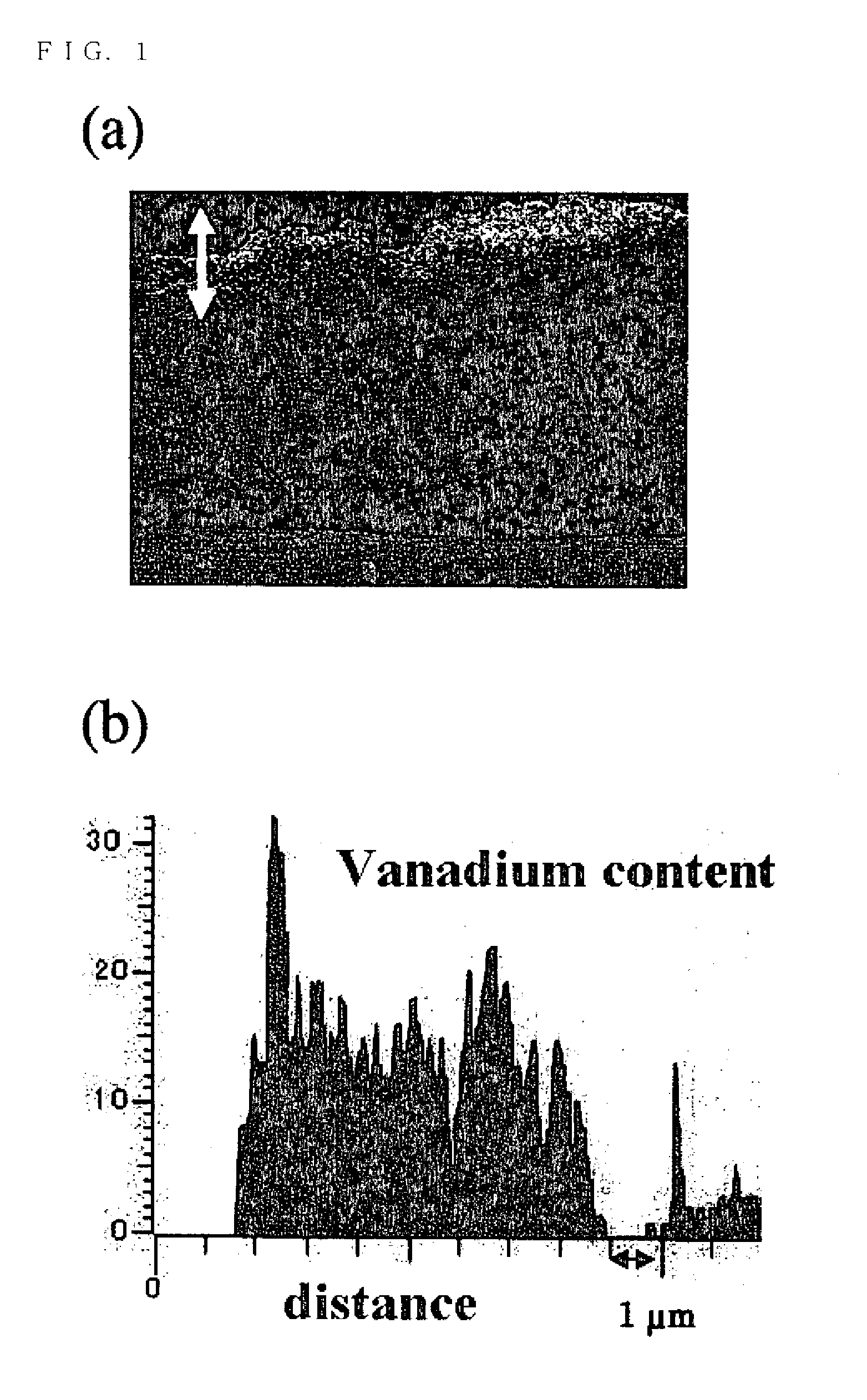
[0023]A plate-like crystalline solid electrolyte Li3.4V0.6Si0.4O4 was manufactured by solid-phase reaction and this was served as a target to which ion impact was exerted with a high frequency magnetron sputtering apparatus (made by Osaka Vacuum Ltd., Type OSV250) at a frequency of 13.56 MHz, the amount of gas flow to be described later, a pressure of 4 Pa, and an output of 150 W for 24 hours. After that, the target was reversed and ion impact was exerted in the same conditions to obtain three types of electricity generating elements.

[0024]Lithium batteries of the Examples 1 to 3 were manufactured by forming current collectors by sputtering platinum on both sides of each electricity generating element. Then, a positive electrode of a direct current power source was connected to one current collector of the respective batteries and a negative electrode was connected to the other current collector; charging was made to a voltage of 4.0 V at a c...

example 4

[0026]An electricity generating element was manufactured in the same conditions as Example 2 except for that exerting time of the ion impact was set to 5 hours in place of 24 hours. Separately, an electrolyte solution was prepared by dissolving LiClO4 in propylene carbonate (referred to as PC) so as to be concentration of 1 M

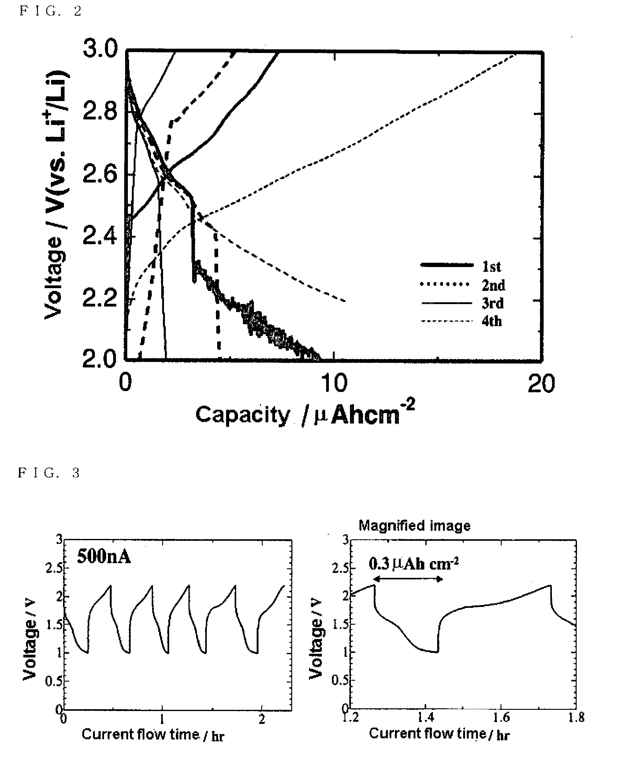
[0027]A positive electrode current collector was formed by sputtering platinum on one surface of the electricity generating element, and lithium metal was faced on the opposite surface through the electrolyte solution as a negative electrode. Then, charge-discharge capacity was measured while operation, in which discharging was performed so that a battery voltage became to 2.0 V at a constant current of 10 nA and charging was performed to become to 3.0 V at the same current, was repeated four times. The measured result is shown in FIG. 2.

[0028]As shown in FIG. 2, it was turned out that a substance formed on the surface of the solid electrolyte by the ion impact ...

example 6

[0033]A laminated body was manufactured in the same conditions as Example 5 except for that a Li—Co—O thin film was formed on the surface of a glass ceramic sheet in place of the Li—Mn—O thin film, and charge-discharge capacity was measured. (Li2CO3+Co3O4) powder (molar ratio 7:5) was used as a target for forming the Li—Co—O thin film. The measured result is shown in FIG. 5. As in the case of Example 5, it showed good charge-discharge characteristics.


PUM

PropertyMeasurementUnit
pressureaaaaaaaaaa
voltageaaaaaaaaaa
exerting timeaaaaaaaaaa

Abstract

Disclosed are an inexpensive all-solid-state lithium battery and a group of batteries having a small internal resistance. The electrode active material of the battery is formed on the surface of a solid electrolyte (it may be a crystal or a glass material) containing lithium ion such as Li3.4V0.6Si0.4O4 and a Li—Ti—Al—P—O based glass material by exerting ion impact, high voltage application (e.g., about 400 V) and the like on the surface to react it. The resultant battery comprises the solid electrolyte and an electrode active material composed of a decomposition product of the solid electrolyte and provided on at least one side of the solid electrolyte. One obtainable by accumulating a plurality of the batteries serves as a group of batteries.

Description

TECHNICAL FIELD[0001]The present invention relates to a lithium battery comprising a solid electrolyte and a manufacturing method thereof.BACKGROUND ART[0002]A lithium battery in widespread used as an advanced battery at present comprises a liquid electrolyte containing an organic solvent. It is known that such an organic solvent causes a decomposition reaction by oxidation or reduction on the surface of an electrode active material. Then, this decomposition reaction causes formation of a resistive layer at an interface between an electrode active material and an electrolyte. The resistive layer irreversibly increases with time or by repetition of charge-discharge reaction to irreversibly increase battery resistance. As a result, battery performance lowers to reduce battery life. Furthermore, the aforementioned organic solvent is inflammable and therefore it is very expensive in providing measures for safety.[0003]Consequently, some proposals have been made to develop batteries comp...

Claims


Application Information

Patent Timeline
Patent Type & Authority Applications(United States)
IPC IPC(8): H01M6/18H01M4/48B01J19/08B01J19/12B05D1/00H01M6/42H01M4/485H01M10/052H01M10/0525H01M10/0562H01M10/0585
CPCH01M4/0407H01M4/049H01M4/13H01M4/485H01M6/42Y10T29/49108H01M10/0562Y02E60/122B01J19/08H01M10/04H01M10/052H01M10/0525Y02E60/10Y02P70/50H01M10/058
Inventor OGUMI, ZEMPACHIIRIYAMA, YASUTOSHIABE, TAKESHIYADA, CHIHIRO
Owner KYOTO UNIV
Why Eureka
Try Eureka