Eureka AIR delivers breakthrough ideas for toughest innovation challenges, trusted by R&D personnel around the world.

Flash Structure for the Camera Function of a Handheld Electronic Device

Active Publication Date: 2013-05-16
LUMINTEC LLC
View PDF1 Cites 17 Cited by
  • Summary
  • Abstract
  • Description
  • Claims
  • Application Information

AI Technical Summary

Benefits of technology

The present invention is a flash structure for the camera function of a handheld electronic device that improves luminance uniformity to enhance the quality of pictures, videos, and real-time images. The flash structure consists of multiple light-emitting elements placed around the camera lens and a ring-shaped or arc-shaped light diffuser to create supplemental lighting. This flash structure is simple in construction and does not increase manufacturing costs. It can improve the overall practicality of the camera module and make it a practical application.

Problems solved by technology

However the designed location of the flash module in conventional camera functions often results in uneven distribution of light, which diminishes the anticipated quality of resulting pictures or videos.

Method used


Image

  • Flash Structure for the Camera Function of a Handheld Electronic Device
  • Flash Structure for the Camera Function of a Handheld Electronic Device
  • Flash Structure for the Camera Function of a Handheld Electronic Device

Examples


Embodiment Construction

[0020]The implementation of the invention is described below through specific embodiments of the invention. Persons skilled in the art can easily understand other advantages and effects of the invention through the description disclosed herein.

[0021]The embodiments of the invention are described below in reference to the accompanying drawings. It should be noted that the drawings are simplified schematic drawings to illustrate the basic ideas of the invention schematically. The diagrams only depict the related structure of the invention and are not drawn according to the actual number, shapes and dimensions of components used in actual implementation, and hence should not be construed as a limitation on the forms, quantities and dimensions of respective components in actual implementation, which may vary based on the actual design needs.

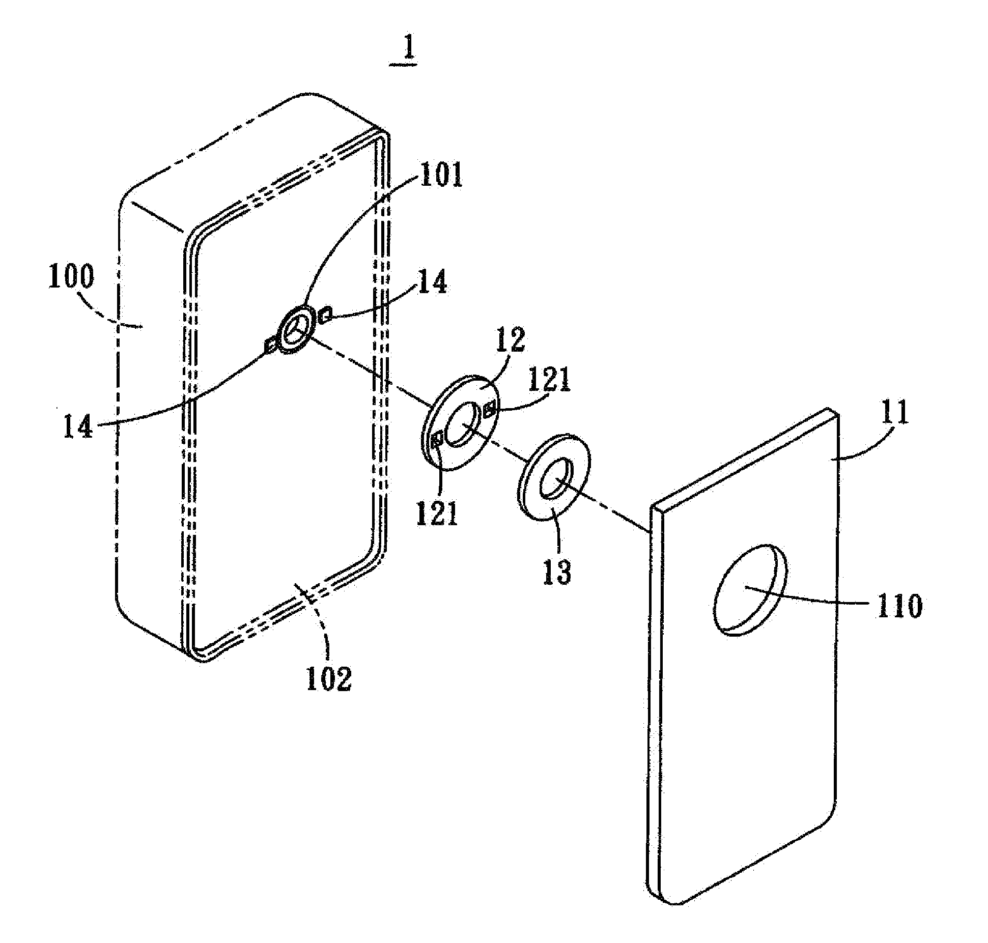
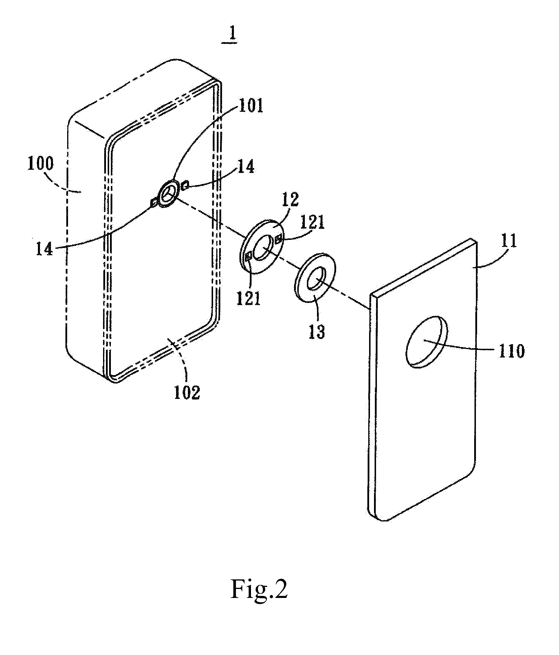
[0022]FIGS. 2, 3 and 4 are respectively an exploded view, an assembled view and a side sectional view of the flash structure for the camera function...


PUM


Abstract

A flash structure for the camera function of a handheld electronic device having at least a camera module as well as an image sensor and a camera lens contained in the camera module, comprising an outer cover, an annular reflector, at least a light diffuser, and one or a plurality of fixed light-emitting elements which are light emitting diodes or electronic flashes to provide continuous or intermittent supplemental light source. The center of the annular reflector passes through the camera lens and is formed on the motherboard of the handheld electronic device, and is arranged with a through-slot. The one or the plurality of light-emitting elements are embedded in the through-slot of the annular reflector, arranged around the camera lens, and electrically connected to the motherboard. The light diffuser is disposed outside the annular reflector, outside the light-emitting element and positioned around the camera lens.

Description

NOTICE OF COPYRIGHT[0001]A portion of the disclosure of this patent document contains material which is subject to copyright protection. The copyright owner has no objection to any reproduction by anyone of the patent disclosure, as it appears in the United States Patent and Trademark Office patent files or records, but otherwise reserves all copyright rights whatsoever.BACKGROUND OF THE PRESENT INVENTION[0002]1. Field of Invention[0003]The present invention relates to a flash structure for camera, more particularly a flash structure for the camera function of a handheld electronic device that has a simple construction and enhances the picture, video and real-time image quality of the handheld electronic device.[0004]2. Description of Related Arts[0005]Nowadays camera module is an essential component in every handheld electronic device. For instance, digital cameras, mobile phones, smartphones, tablet computers, PDA and laptop computers all come with at least a basic camera module t...

Claims


Application Information

Patent Timeline
IPC IPC(8): G03B15/05
CPCG03B2215/0503G03B15/05G03B2215/0575G03B2215/0567
Inventor YEH, YANG-SHANTAO, CHI-WEI
Owner LUMINTEC LLC
Why Eureka
Eureka Blog
Learn More