Battery Pack with a Heat Dissipation Structure

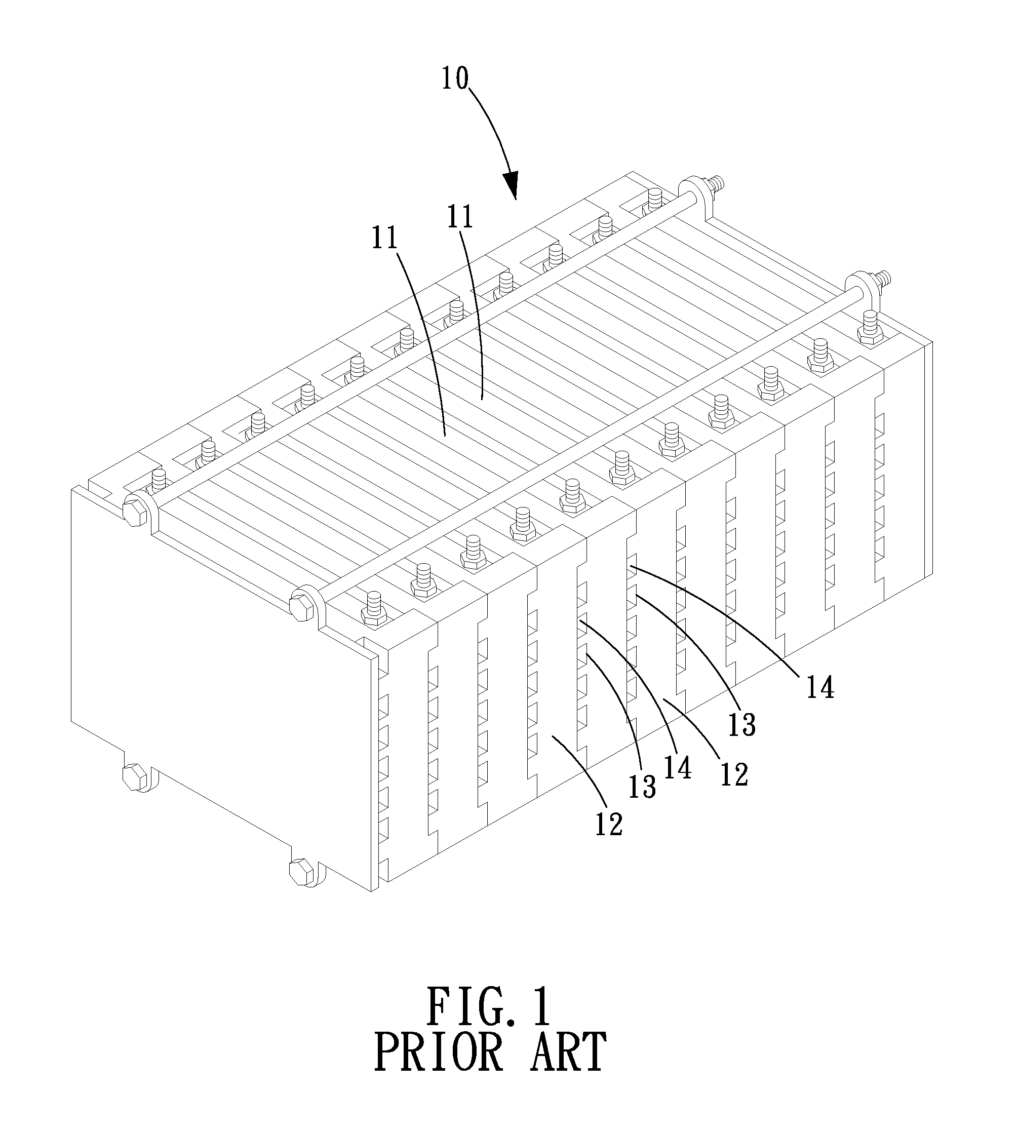
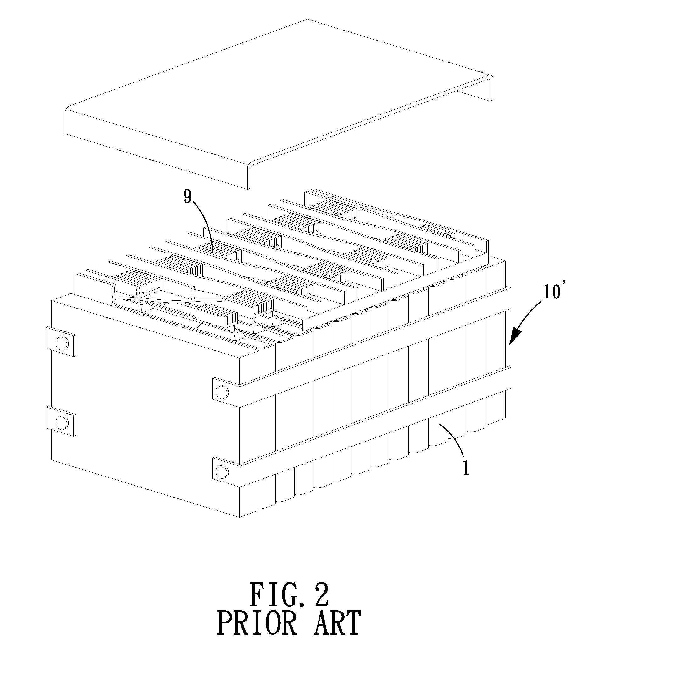
a battery pack and heat dissipation technology, applied in the field of battery packs, can solve the problems of poor heat dissipation and poor heat dissipation of the conventional battery pack b>10/b>′, and achieve the effect of smooth exchange and avoiding heat accumulation

Active Publication Date: 2013-05-16
BIXIANG ELECTRIC ENERGY HIGH SCI & TECHCO
View PDF1 Cites 2 Cited by
  • Summary
  • Abstract
  • Description
  • Claims
  • Application Information

AI Technical Summary

Benefits of technology

[0012]The primary objective of the present invention is to provide a battery pack with a heat dissipation structure which comprises two battery modules spaced by a distance, avoiding the heat accumulation due to direct contact of the two battery modules, in addition between the two battery modules is formed a heat dissipation channel, allowing the hot air in the heat dissipation channel to be smoothly exchanged with the cool air outside the battery pack, cooling down the temperature.
[0013]The secondary objective of the present invention is to provide a battery pack with a heat dissipation structure in which heat dissipation fins are collectively disposed on the left surfaces and the right surfaces of the respective battery modules, not only avoiding the heat accumulation in the inner surface but also facilitating the space arrangement of the battery pack when in use, for example, the heat dissipation fins can be arranged toward a place with better ventilation.

Problems solved by technology

The disadvantage of this conventional battery pack 10′ is that the battery modules 1 are rested against one another, leaving no space between the battery modules 1, which is not good for heat dissipation.
Therefore, the heat dissipation of this conventional battery pack 10′ is not good.

Method used


Image

  • Battery Pack with a Heat Dissipation Structure
  • Battery Pack with a Heat Dissipation Structure
  • Battery Pack with a Heat Dissipation Structure

Examples


Embodiment Construction

[0026]The present invention will be clearer from the following description when viewed together with the accompanying drawings, which show, for purpose of illustrations only, the preferred embodiment in accordance with the present invention.

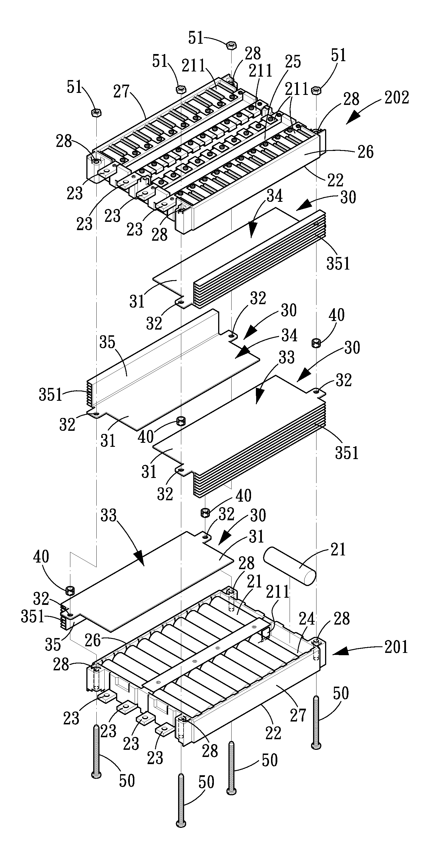
[0027]Referring to FIGS. 3-6, a battery pack with a heat dissipation structure in accordance with the present invention comprises two battery modules 201, 202, four heat dissipation elements 30, four spacing sleeves 40 that are combined by four screws 50, and the four heat dissipation elements 30 and the four spacing sleeves 40 are disposed between the two battery modules 201, 202.

[0028]Each of the battery modules 201, 202 includes plural battery cells 21 that are electrically connected through metal connecting strips 211 in a rectangular frame 22 and have common output terminals 23. The frame 22 includes an inner surface 24, an outer surface 25, a left surface 26 and a right surface 27. Each of the battery cells 21 has a side surface exposed out...


PUM

PropertyMeasurementUnit
distanceaaaaaaaaaa
heataaaaaaaaaa
heat dissipationaaaaaaaaaa

Abstract

A battery pack with a heat dissipation structure comprises two battery modules, four heat dissipation elements, and four spacing sleeves that are combined by four screws. The four heat dissipation elements and the four spacing sleeves are disposed between the two battery modules. The dissipation elements are in direct contact with the respective battery modules, so that the heat of the respective battery module will be conducted to the heat dissipation plates then dissipated into the air through the heat dissipation fins of the heat dissipation plates. Between the two battery modules is formed a heat dissipation channel, which can avoid the heat accumulation due to direct contact of the two battery modules while allowing the hot air in the heat dissipation channel to be exchanged to the cool air outside the battery pack.

Description

[0001]This application is a continuation in part of U.S. patent application Ser. No. 12 / 950,084, now pending, which claims the benefit of the earlier filing date of Nov. 19, 2010. Claim 1 of this application is revised from claim 1 of the U.S. patent application Ser. No. 12 / 950,084.BACKGROUND OF THE INVENTION[0002]1. Field of the Invention[0003]The present invention relates to a battery pack, and more particularly to a battery pack with a heat dissipation structure.[0004]2. Description of the Prior Art[0005]Referring to FIG. 1, a conventional battery pack 10 disclosed in U.S. Pub. No. 20070037051 comprises plural battery cells 11, and plural spacers 12 arranged between the respective battery cells 11. Each of the spacers 12 is formed with plural concavo-convex structures 13, so that plural air channels 14 will be formed after the respective battery cells 11 and the spacers 12 are assembled, facilitating the heat dissipation of the battery pack 10.[0006]It is to be noted that, the he...

Claims


Application Information

Patent Timeline
Patent Type & Authority Applications(United States)
IPC IPC(8): H01M10/50H01M50/213H01M50/262
CPCH01M10/5004H01M10/503H01M10/5046H01M2/1077H01M2/1016H01M2/105H01M10/5055H01M10/6551H01M10/6555H01M10/643H01M10/613Y02E60/10H01M50/213H01M50/262
Inventor WU, DONALD P. H.
Owner BIXIANG ELECTRIC ENERGY HIGH SCI & TECHCO
Why Eureka
Try Eureka