Controller and control method for vehicle

a control method and vehicle technology, applied in the direction of digital data processing details, mechanical equipment, instruments, etc., can solve the problems of increasing shift shock, delay in shifting and drivability, and inability to cancel inertia torque through engine torque reduction control, etc., to suppress racing, smooth torque exchange, and suppress shift shock

Inactive Publication Date: 2014-02-13
TOYOTA JIDOSHA KK
View PDF14 Cites 6 Cited by
  • Summary
  • Abstract
  • Description
  • Claims
  • Application Information

AI Technical Summary

Benefits of technology

[0013]In the controller, the shift control unit may be configured to determine a torque capacity of a predetermined engagement device, selected from between the engaged-side engagement device and the released-side engagement device, using a torque share, including a tie-up rate, as the torque share. The shift control unit is configured to change the predetermined engagement device on the basis of the shift pattern. With this configuration, at the time when the shift target values significantly change, such as the start of inertia phase and the end of inertia phase during shifting, if the control operation amount of the torque capacity of one of the released-side engagement device and the engaged-side engagement device is zero, an actual torque on the rotating member on the output shaft side or an actual speed of the rotating member on the input shaft side more rapidly varies than the shift target values due to a response delay, variations, and the like, of an actual torque capacity with respect to the control operation amount or the rotation speed of the rotating member on the input shaft side steeply increases and, as a result, a shift shock may increase. In contrast, by controlling an exchange of the torque toward tie-up side, it is possible to smoothly exchange the torque, it is possible to share the rapidly varied amount at the predetermined engagement device or it is possible to suppress the racing, so it is possible to suppress a shift shock that may increase at the time when the shift target values significantly change. In addition, the predetermined engagement device is changed on the basis of the shift pattern, so it is possible to further appropriately suppress a shift shock in accordance with the shift pattern.
[0014]In the controller, the shift control unit may be configured to set the released-side engagement device as the predetermined engagement device when the shift pattern is a power-on upshift or a power-off downshift. The shift control unit is configured to set the engaged-side engagement device as the predetermined engagement device when the shift pattern is a power-off upshift or a power-on downshift. With this configuration, even when the torque capacities of the engagement devices are increased in order to cause tie-up, it is less likely to influence the transmission torque and, by extension, the torque on the rotating member on the output shaft side or it is less likely to influence the progress of the shift. For example, when the timing at which the torque shares are varied is set to the timing before the start of inertia phase in a power-on upshift or a power-off downshift, by adding a tie-up amount to the torque capacity of the released-side engagement device, a rapid variation in actual torque on the rotating member on the output shaft side or a rapid variation in the speed of the rotating member on the input shaft side after the start of inertia phase is appropriately suppressed without influencing the torque on the rotating member on the output shaft side before the start of inertia phase. On the other hand, when the timing at which the torque shares are varied is set to the end of inertia phase in a power-off upshift or a power-on downshift, by adding a tie-up amount to the torque capacity of the engaged-side engagement device, racing, or the like, of the rotating member on the input shaft side at the end of inertia phase is appropriately suppressed while making it less likely to influence the progress of the shift through releasing of the released-side engagement device.

Problems solved by technology

However, in the technique described in JP 2000-97325 A, in order to cancel inertia torque during inertia phase (in other words, in order for output shaft torque during inertia phase not to substantially vary), the hydraulic pressure of the released-side engagement device is gradually decreased for release and is then temporarily gradually increased for engagement again, so there is a possibility that completion of a shift delays and drivability deteriorates.
That is, in the technique described in JP 2000-97325 A, the equation of motion is solved for a current engine torque, so, in the shift model control described in JP 2000-97325 A, it is not possible to cancel inertia torque through engine torque reduction control instead of a temporal increase in hydraulic pressure of the released-side engagement device.
However, in this case, the overall shift model control collapses, and a solution is derived from the equations of motion again, so eventually there is a possibility that completion of a shift delays, a shift shock increases and drivability deteriorates.
Therefore, it is not possible to solve the equations of motion, and it is not possible to shift the automatic transmission using shift model control.
With this configuration, in a situation that, when the three control operation amounts need to be determined in order to achieve the two shift target values, it is not possible to determine those control operation amounts unless a constraint condition is set.
Specifically, when only one of the torque capacity of the engaged-side engagement device and the torque capacity of the released-side engagement device is set as the constraint condition, there is a possibility that tie-up or racing of a rotating member may occur.
In addition, when the torque on the rotating member on the input shaft side is set as the constraint condition, there is a possibility that it is not possible to execute control for temporarily varying the output torque of a driving force source.

Method used


Image

  • Controller and control method for vehicle
  • Controller and control method for vehicle
  • Controller and control method for vehicle

Examples


first embodiment

[0029]Hereinafter, an embodiment (first embodiment) of the invention will be described with reference to the accompanying drawings.

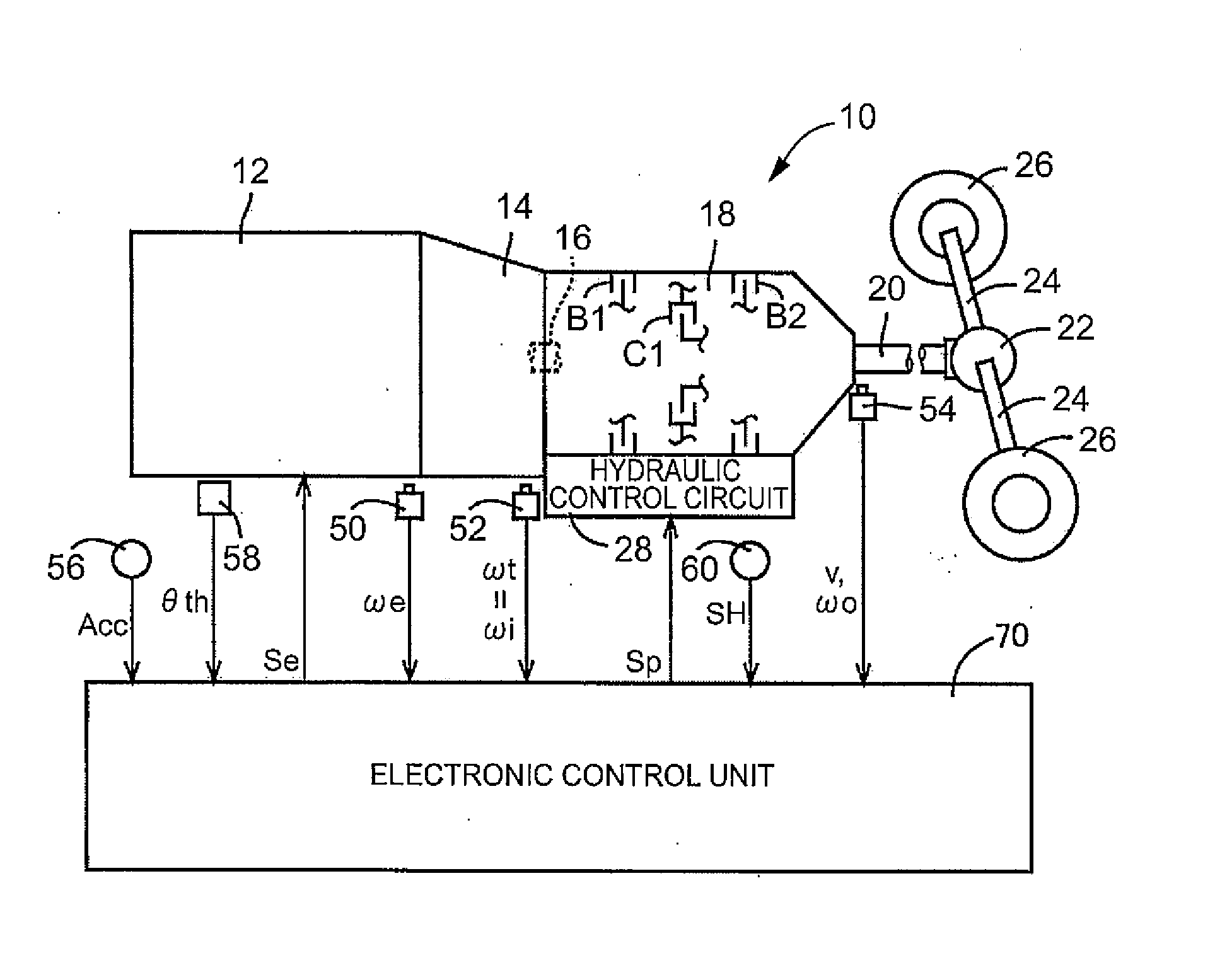
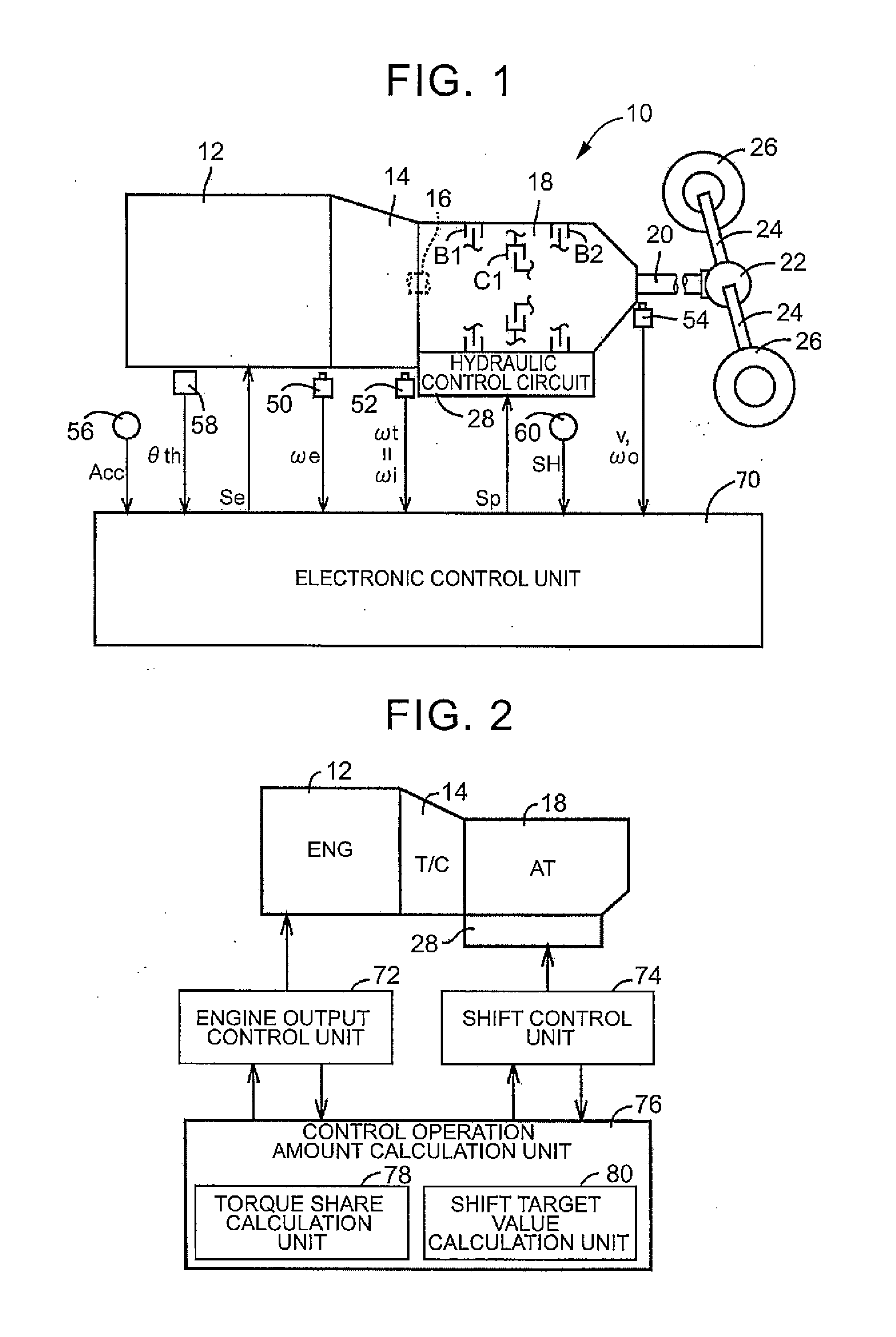
[0030]FIG. 1 is a view that illustrates the schematic configuration of a power transmission path from an engine 12 mounted on a vehicle 10, to which the invention is applied, to drive wheels 26, and is a view that illustrates a relevant portion of a control system provided in the vehicle 10. In FIG. 1, power generated by the engine 12 that serves as a driving force source is passed through a torque converter 14 and input from an input shaft 16 to the automatic transmission 18, and then transmitted from an output shaft 20 of the automatic transmission 18 to the right and left drive wheels 26 sequentially via a differential gear unit (differential gear) 22, a pair of axles (drive shafts) 24, and the like.

[0031]The automatic transmission 18 is a known planetary gear-type automatic transmission that includes a single set or multiple sets of planetary gear un...

second embodiment

[0061]Next, another embodiment (second embodiment) of the invention will be described. Like reference numerals denote mutually common portions between the embodiments in the following description, and the description thereof is omitted.

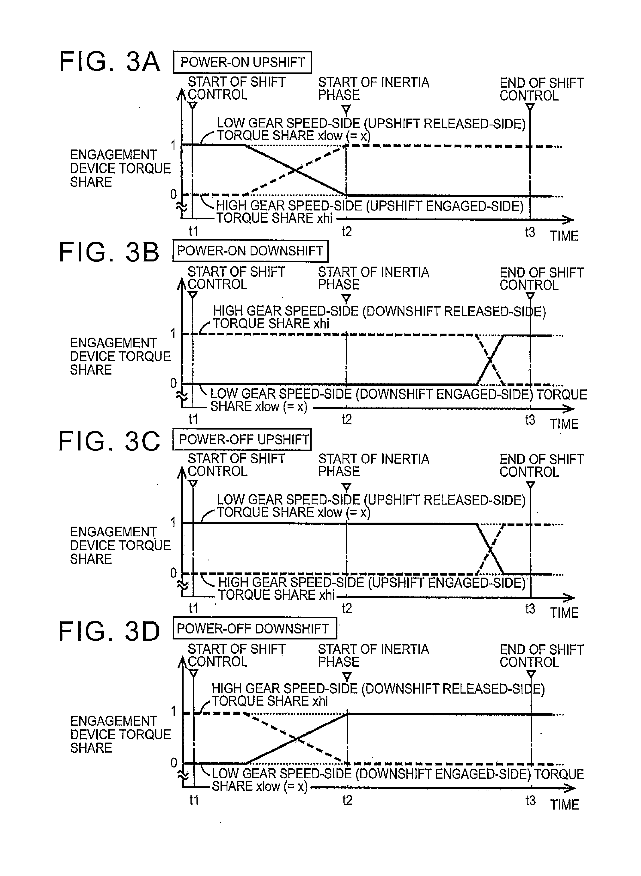
[0062]In the above-described first embodiment, as shown in the time chart of FIG. 5, the target value of the transmission output torque To during inertia phase is determined on the assumption that it is possible to cancel inertial torque in engine torque reduction control. Incidentally, there is presumably a case where only part of inertia torque can be apparently cancelled depending on the shift pattern, each pair of speeds, the vehicle speed V at the time of the shift, the state of the engine 12, and the like. Therefore, in such a case, the shift target value calculation unit 80 according to the second embodiment sets the target value of the transmission output torque To during inertia phase on the assumption that it is possible to cancel only part ...


PUM


Abstract

In a vehicle control, an automatic transmission is shifted using a predetermined shift model, which determines control operation amounts for achieving shift target values, by setting the shift target values on the basis of a torque on an output shaft-side rotating member and a speed variation amount of an input shaft-side rotating member, setting the control operation amounts on the basis of a torque on the input shaft-side rotating member, a torque capacity of an engaged-side engagement device during shifting and a torque capacity of a released-side engagement device during shifting and setting torque shares of a transmission torque between the engaged-side engagement device and the released-side engagement device during shifting when the transmission torque is converted to the torque on the input shaft-side rotating member, and timing at which the torque shares are varied is changed on the basis of a shift pattern.

Description

INCORPORATION BY REFERENCE[0001]The disclosure of Japanese Patent Application No. 2012-175173 filed on Aug. 7, 2012 including the specification, drawings and abstract is incorporated herein by reference in its entirety.BACKGROUND OF THE INVENTION[0002]1. Field of the Invention[0003]The invention relates to a controller and control method for a vehicle, which execute shift control over an automatic transmission, and, more particularly, to a technique for shifting an automatic transmission with the use of a shift model.[0004]2. Description of Related Art[0005]There is well known an automatic transmission that includes a plurality of engagement devices, which transmit rotation and torque between an input shaft that receives power from a driving force source and an output shaft that transmits power to drive wheels, and that is shifted by switching between engaged and released states of each of the engagement devices. Generally, in such an automatic transmission, a required value (that i...

Claims


Application Information

Patent Timeline
Patent Type & Authority Applications(United States)
IPC IPC(8): B60W10/11B60W10/06
CPCB60W10/06B60W10/11F16H61/061F16H2059/147F16H2059/148F16H2059/425F16H2061/009
Inventor MASUNAGA, SEIJIHASEGAWA, YOSHIOOTA, KEISUKE
Owner TOYOTA JIDOSHA KK
Why Eureka
Try Eureka