Inflatable minimally invasive system for delivering and securing an annular implant

a minimally invasive, annular implant technology, applied in the field of delivery and securing annular implants, can solve the problems of structural annulus, inability to fully appreciate the exact amount of narrowing required for the desired effect, and interruption of normal physiologic flow, etc., to achieve the effect of assessing the physiologic effect, altering the position, size and shap

Inactive Publication Date: 2013-05-16
ST JUDE MEDICAL CARDILOGY DIV INC
View PDF8 Cites 135 Cited by
  • Summary
  • Abstract
  • Description
  • Claims
  • Application Information

AI Technical Summary

Benefits of technology

[0030]In a preferred embodiment, the ring core runs around the circumference of the device, then through a cinching mechanism. As the two ends of the ring core pass through the cinching mechanism, they become cinching cords, which pass up through the trocar of the device. The flared gunbarrel elements and the cinching cords allow the user to control the size of the ring core. The flared gunbarrel elements tend to expand the ring core diameter, whereas the cinching mechanism allows the user to reduce the ring core diameter or shape. The device user pulls on the exposed ends of the cinching cords located at the distal end of the trocar to reduce the diameter of the ring core. When the device user releases tension on the cinching cords, a locking mechanism prevents the ring core from relaxing and the ring diameter from consequently expanding, unless desired. Through a combination of extension of the gunbarrel elements from the trocar and tension exerted on the cinching cords, the device user can tailor the size and shape of the ring core. The locking mechanism may feature a means by which the user can release the lock, so that the ring may be readjusted as many times as necessary to achieve the desired result.

Problems solved by technology

In many physiologic settings, dysfunction may result from a structural annulus which is either too large or too small.
Often, such surgical procedures require interruption in the normal physiologic flow of blood, other physiologic fluids, or other structural contents through the annulus or structure.
The exact amount of the narrowing required for the desired effect often cannot be fully appreciated until physiologic flow through the annulus or structure is resumed.
However, the ideal prosthetic valve has yet to be designed, which attests to the elegant form and function of the native heart valve.
However, the repairs of rheumatic insufficient valves have not met with good results due to the underlying valve pathology and the progression of the disease.
However, the ideal prosthetic valve has yet to be designed, which attests to the elegant form and function of the native heart valve.
However, the repairs of rheumatic insufficient valves have not met with good results due to the underlying valve pathology and the progression of the disease. insufficiency, resulting in a focal area of regurgitation.
The problem encountered in mitral valve repair is the surgeon's inability to fully assess the effectiveness of the repair until the heart has been fully closed, and the patient is weaned off cardiopulmonary bypass.
This increases overall operative, anesthesia, and bypass times, and therefore increases the overall operative risks.
If the implant used to reduce the annulus is larger than the ideal size, mitral insufficiency may persist.
If the implant is too small, mitral stenosis may result.
“Gas bloat,” which causes the inability to belch, is also a common complication of over-narrowing of the gastro-esophageal junction.
This surgical strategy has the disadvantage of requiring invasive surgery to access the exterior of the stomach, and both sides thereof in the case of stapling with a required anvil, in addition to the lack of post operative adjustability of the pouch size.
These techniques are disadvantageous again due to the surgically invasive procedure for applying the bands externally to the stomach, in addition to the high incidence of necrosis as the result of constricting the tissues.
Significant clinical and logistical problems attend both of these existing technologies.
In the case of the coronary sinus procedures, percutaneous access to the coronary sinus is technically difficult and time consuming to achieve, with procedures which may require several hours to properly access the coronary sinus.
Moreover, many of these procedures employ incomplete annular rings, which compromise their physiologic effect.
Moreover, the coronary sinus approach does not address the correction of diseased annular tissues, particularly on the posterior annulus of the mitral valve.
Such procedures are typically not effective for improving mitral regurgitation by more than one clinical grade.
Finally, coronary sinus procedures carry the potentially disastrous risks of either fatal tears or catastrophic thrombosis of the coronary sinus.
Similarly, percutaneous procedures which employ sutures, clips, or other devices to affix the anterior mitral leaflets to the posterior mitral leaflets also have limited reparative capabilities.
Such procedures are also typically ineffective in providing a complete repair of mitral regurgitation.
These procedures also fail to address the pathophysiology of the dilated mitral annulus in ischemic heart disease.

Method used


Image

  • Inflatable minimally invasive system for delivering and securing an annular implant
  • Inflatable minimally invasive system for delivering and securing an annular implant
  • Inflatable minimally invasive system for delivering and securing an annular implant

Examples


Embodiment Construction

[0045]As required, detailed embodiments of the present invention are disclosed herein; however, it is to be understood that the disclosed embodiments are merely exemplary of the invention which may be embodied in various forms. Therefore, specific structural and functional details disclosed herein are not to be interpreted as limiting, but merely as a basis for the claims and as a representative basis for teaching one skilled in the art to variously employ the present invention in virtually any appropriately detailed structure.

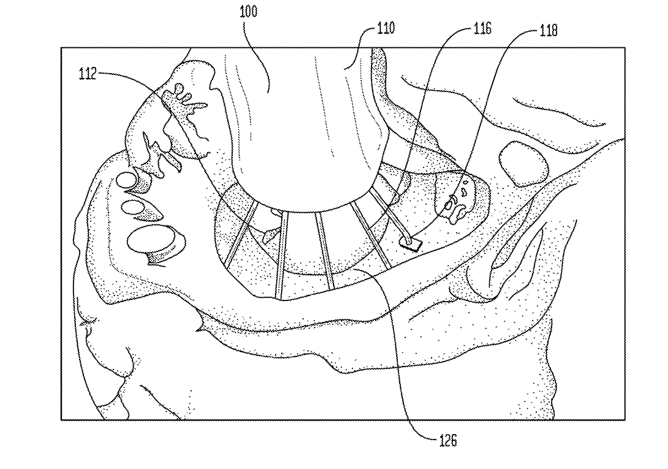
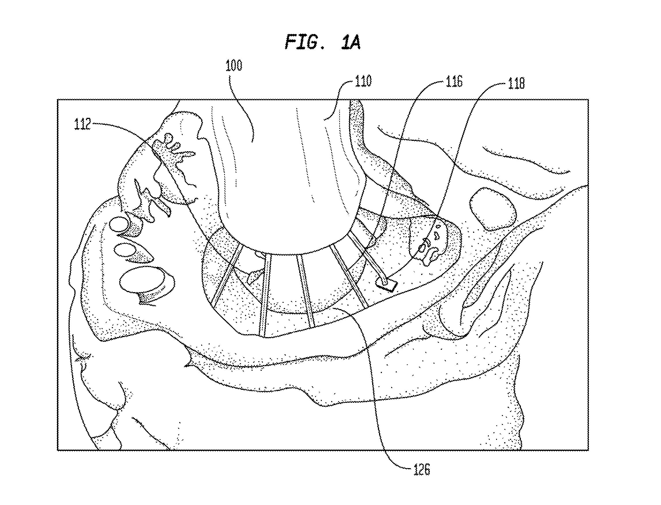
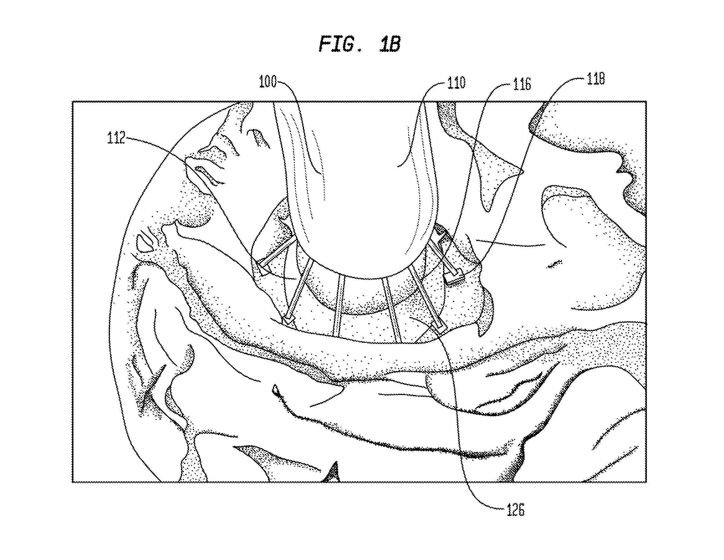
[0046]An improved annular implant delivery device has been developed for use in delivering an annular implant to an annulus in a patient's body. The delivery device can be housed in an endoscopic sheath or trocar or other covering, which is inserted into a patient to deliver an annular implant to an annulus in a minimally invasive procedure. The delivery procedure can be performed endoscopically, percutaneously, or with an endoscope placed within a body cavity...


PUM


Abstract

A delivery device for an annular implant that includes a balloon expansion mechanism and an annular implant having an adjustable dimension. The balloon expansion mechanism includes an inflation tube attached to a non-occluding balloon collar which is supported by trusses radially extending from a trocar. The annular implant further includes a flexible ring core, contiguous coiled spacers, and anchoring blocks. The flexible ring core is adjusted via a cinching mechanism. The anchoring blocks are spaced along the ring core by the contiguous coiled spacers, which keeps the distance between each pair of anchoring blocks equidistant as the ring core diameter is manipulated by the device user. The annular implant can also include gunbarrel elements housed in the trocar. Each gunbarrel element contains a gunbarrel pusher which drives an attachment element into the annular implant and annular tissue.

Description

CROSS REFERENCE TO RELATED APPLICATIONS[0001]The present application is a divisional of U.S. patent application Ser. No. 12 / 702,502, filed Feb. 9, 2010, which claims the benefit of the filing date of U.S. Provisional Patent Application No. 61 / 151,061, filed Feb. 9, 2009, which applications are expressly incorporated herein by reference in their entirety.FIELD OF THE INVENTION[0002]The present invention relates generally to the delivery of an implantable device, and more particularly to methods and devices for delivering and securing an annular implant to control the internal circumference of an annulus.BACKGROUND OF THE INVENTION[0003]Many anatomic structures in the mammalian body are hollow passages in which walls of tissue define an annulus, which serves as a conduit for blood, other physiologic fluids, nutrient matter, or waste matter passing within the structure. In many physiologic settings, dysfunction may result from a structural annulus which is either too large or too small...

Claims


Application Information

Patent Timeline
Patent Type & Authority Applications(United States)
IPC IPC(8): A61F2/24
CPCA61F2/2439A61B17/0644A61B2017/0414A61B17/0401A61B2017/0649A61F2002/30537A61M2025/1097A61B17/0487A61F2/2466A61F2/2433A61B2017/0647A61F2/2445A61B2017/00243A61F2250/0004A61B2017/0496A61B17/064A61F2/0031A61F2250/0059A61F2220/0016A61F2250/001
Inventor CARTLEDGE, RICHARD G.CARTLEDGE, JOHN P.BADIA, JAMESMCCREA, JAMESBAEZ, LUISBENTLEY, PETER
Owner ST JUDE MEDICAL CARDILOGY DIV INC
Why Eureka
Try Eureka