Power amplifier and amplification method thereof

Inactive Publication Date: 2013-05-23
ELECTRONICS & TELECOMM RES INST
View PDF8 Cites 15 Cited by
  • Summary
  • Abstract
  • Description
  • Claims
  • Application Information

AI Technical Summary

Benefits of technology

[0005]The present invention provides a power amplifier having high efficiency an

Problems solved by technology

In such devices, many components oper

Method used


Image

  • Power amplifier and amplification method thereof
  • Power amplifier and amplification method thereof
  • Power amplifier and amplification method thereof

Examples


Embodiment Construction

[0028]Preferred embodiments of the present invention will be described below in more detail with reference to the accompanying drawings. The present invention may, however, be embodied in different forms and should not be constructed as limited to the embodiments set forth herein. Rather, these embodiments are provided so that this disclosure will be thorough and complete, and will fully convey the scope of the present invention to those skilled in the art.

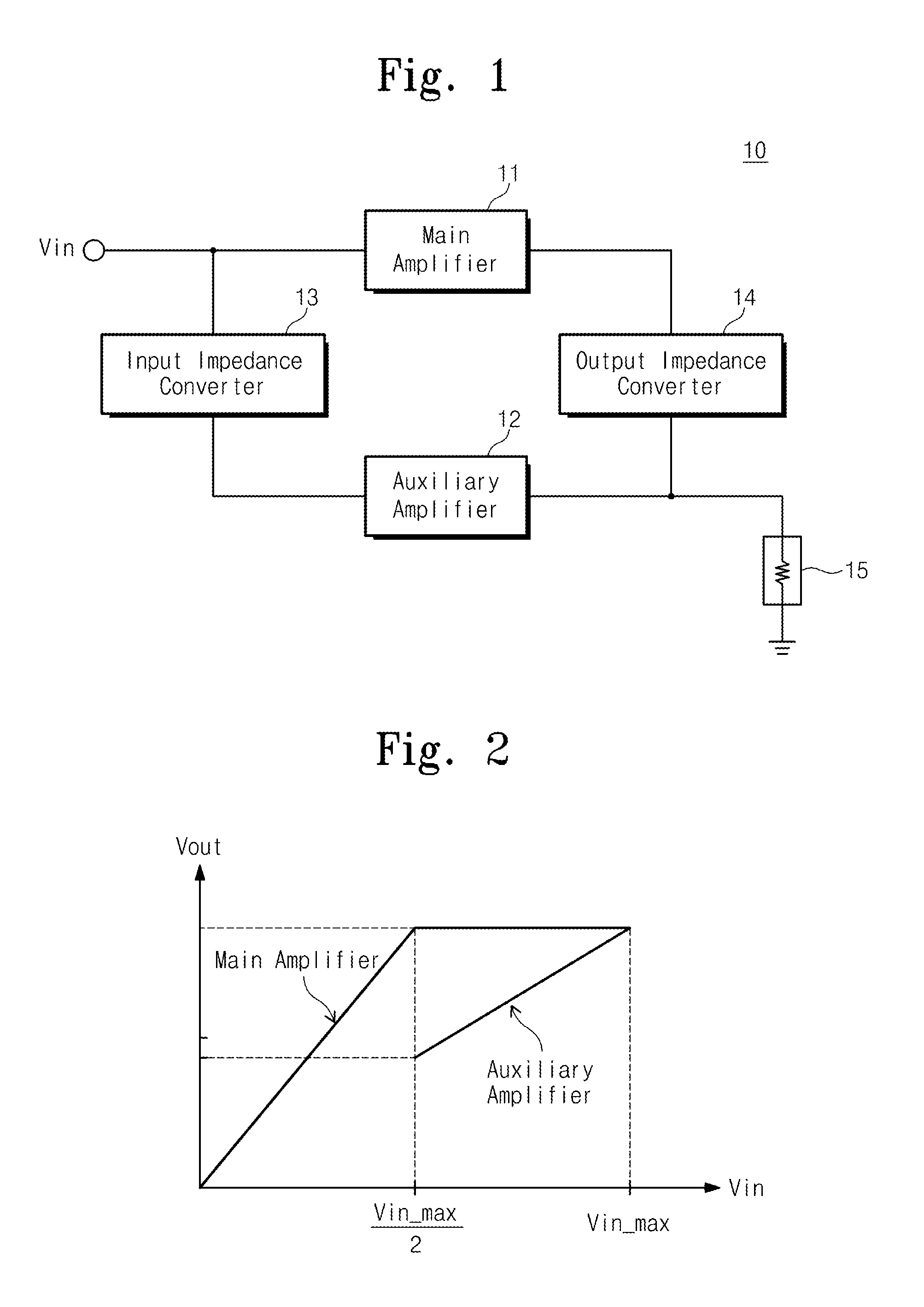
[0029]FIG. 1 is a block diagram illustrating a power amplifier according to an embodiment of the present invention. Referring to FIG. 1, the power amplifier 10 includes a main amplifier 11, an auxiliary amplifier 12, an input impedance converter 13, an output impedance converter 14, and a load 15. That is, the power amplifier 10 is configured through the Doherty method. Once an input voltage Vin is input to the power amplifier 10, it is distributed into the main amplifier 11 and the auxiliary amplifier 12 through a voltage distrib...


PUM


Abstract

Provided are a power amplifier and a method thereof. The power amplifier power amplifier includes: a main amplifying unit receiving power; an auxiliary amplifying unit connected in parallel to the main amplifying unit; and a balloon transformer combined with the main amplifying unit and the auxiliary amplifying unit. Respectively different bias voltages are applied to the main amplifying unit and the auxiliary amplifying unit.

Description

CROSS-REFERENCE TO RELATED APPLICATIONS[0001]This U.S. non-provisional patent application claims priority under 35 U.S.C. §119 of Korean Patent Application No. 10-2011-0121476, filed on Nov. 21, 2011, the entire contents of which are hereby incorporated by reference.BACKGROUND OF THE INVENTION[0002]The present invention disclosed herein relates to a power amplifier and an amplification method thereof.[0003]Due to the recent development of wireless communication system techniques, an integrated design system that integrates a plurality of systems into one device is generally used. In such devices, many components operate and consume power simultaneously. Thus, a highly efficient power amplifier is required to increase the efficient use of power. Moreover, since a digital modulated signal used in a wireless communication system has a high peak-to-average power ratio, power amplifiers require both high efficiency and excellent linearity.[0004]In order to maintain power amplifier linear...

Claims


Application Information

Patent Timeline
IPC IPC(8): H03F3/68
CPCH03F1/0261H03F1/0288H03F2200/541H03F2200/537H03F3/211H03F1/02H03F3/68
Inventor CHOI, YUN HORYU, NAM SIK
Owner ELECTRONICS & TELECOMM RES INST
Why Eureka
Try Eureka