Image processing device for defect inspection and image processing method for defect inspection

a technology of image processing device and defect inspection, which is applied in the field of defect inspection system, can solve the problems of limited practicability and difficulty in accurately inspecting specimen defects

Inactive Publication Date: 2013-05-23
SUMITOMO CHEM CO LTD
View PDF2 Cites 30 Cited by
  • Summary
  • Abstract
  • Description
  • Claims
  • Application Information

AI Technical Summary

Benefits of technology

[0033]As described above, the present invention allows a plurality of data to be obtained as data taken at different imaging angles for an identical position of a specimen. For this reason, the present invention achieves the effect of detecting various types of defects on the specimen, by reference to the plurality of data.

Problems solved by technology

However, practical implementation thereof is limited because it is necessary to highly accurately arrange the optical system (line sensor 501, light source 503, and light shield 504).
However, the dark field method has the problem that it is difficult to accurately inspect the defect of the specimen, because it is difficult to arrange the optical system in practice as described above.

Method used


Image

  • Image processing device for defect inspection and image processing method for defect inspection
  • Image processing device for defect inspection and image processing method for defect inspection
  • Image processing device for defect inspection and image processing method for defect inspection

Examples


examples

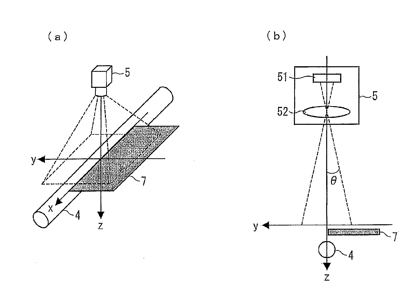
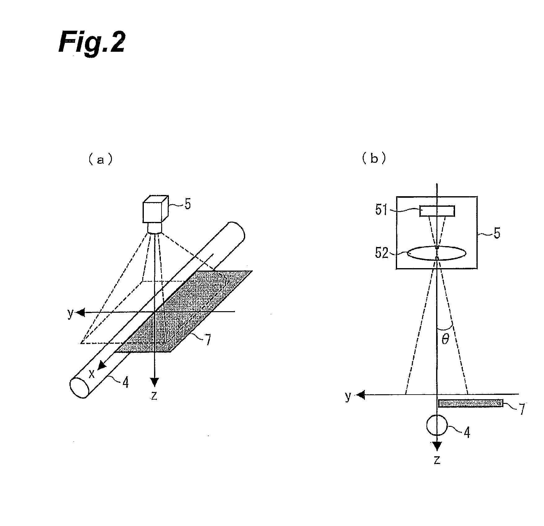
[0153]The below will describe an example in which the RT-LCI processing was performed on the image data taken by the area camera 5, in the defect inspection system 1 shown in FIG. 3. The main body of the area camera 5 used was a double-speed progressive scan monochrome camera module (XC-FIR50 available from Sony Corporation). Furthermore, the lens of the area camera 5 used was a lens (focal length f=35 mm) available from Tamuron Co., Ltd., with a 5 mm extension tube. The number of pixels of the area camera 5 is 512×480 pixels and the resolution per pixel is 70 μm / pixel. The area camera 5 was focused on the surface of the specimen. The frame rate of the area camera 5 was 60 FPS and imaging was performed in the ordinary TV format. The imaging was performed for eight seconds with the area camera and the RT-LCI processing was performed on 480 images. The conveyance speed of the conveyor 3 was set at 4.2 mm / sec. Namely, the specimen 2 was set to move 70 μm per frame. A 22-kHz high-freque...

modification examples

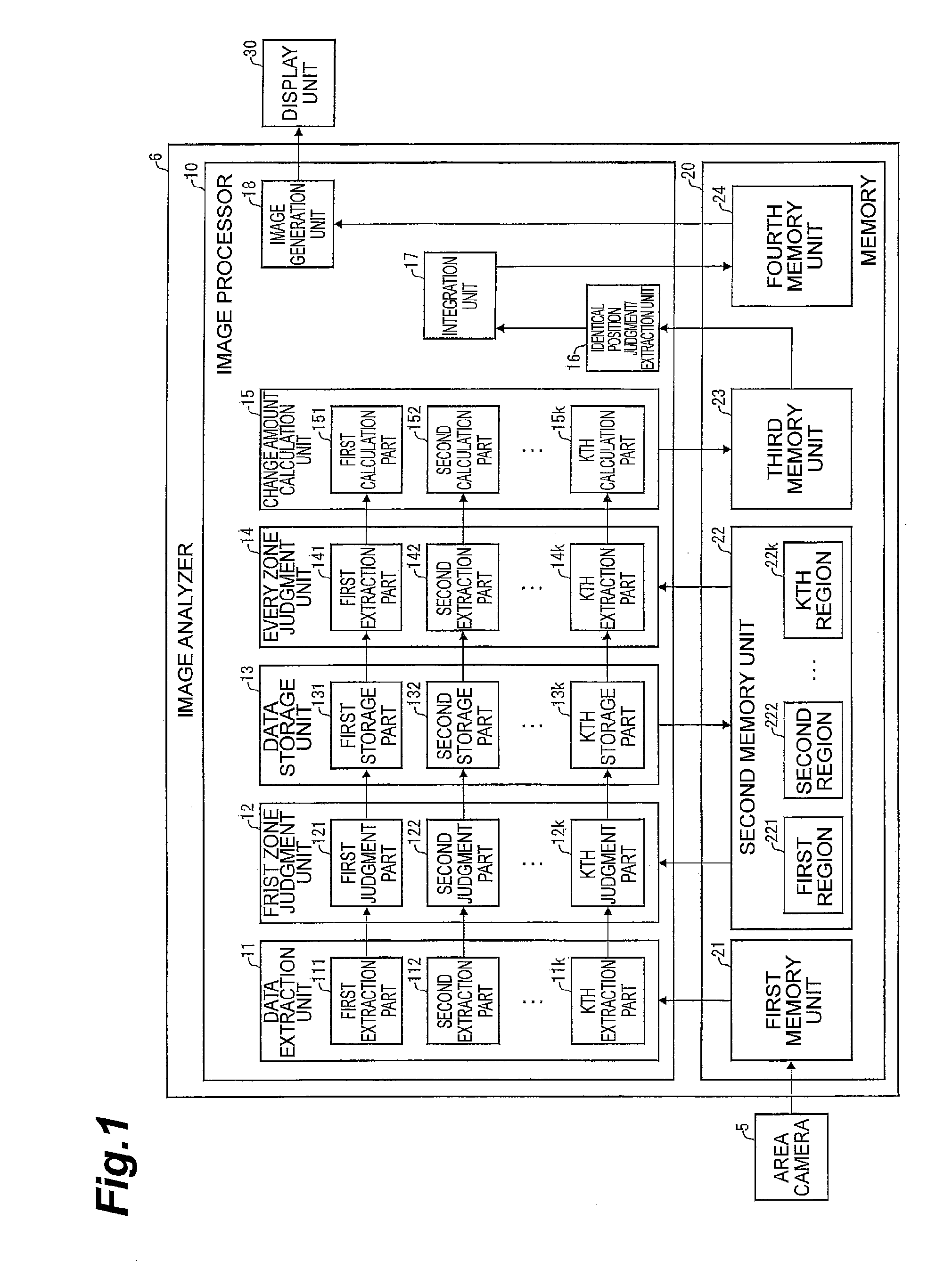
[0165]The change amount calculation unit 15 may be configured so that the number of rows and the number of columns in the differential operator used can be properly set in accordance with the number of lines of the line-composited image data stored in the second memory unit 22. Furthermore, the emphasized image data generated as the result of calculation by the change amount calculation unit 15 does not have to be limited to the data composed of one line as described above, but may be composed of a plurality of lines, as the result of the calculation.

[0166]In the above-described embodiments and examples the change amount calculation unit 15 calculated the longitudinal brightness gradients, but the present invention does not have to be limited to this; for example, the change amount calculation unit 15 may be configured to calculate lateral brightness gradients.

[0167]In the above-described embodiments and examples the defect inspection image data was generated in accordance with the ...


PUM

PropertyMeasurementUnit
half angleaaaaaaaaaa
distanceaaaaaaaaaa
distanceaaaaaaaaaa

Abstract

An image processing device for defect inspection that processes image data taken continually in time from a moving molded sheet with an area camera, having a data extraction unit extracting line data at an identical position from each different image data, for a plurality of different positions on the image data; a data storage unit arranging the plurality of line data in time series for each of the positions on the image data to generate a plurality of line-composited image data; a change amount calculation unit performing a differential operator operation on the plurality of line-composited image data to generate a plurality of emphasized image data; an identical position judgment / extraction unit extracting data indicating an identical position of the molded sheet from the plurality of emphasized image data; and an integration unit accumulating, at respective pixels, brightness values of the extracted emphasized image data to generate defect inspection image data.

Description

TECHNICAL FIELD[0001]The present invention relates to a defect inspection system for inspection of a defect in a specimen such as a sheet-like specimen, and to an imaging device for defect inspection, an image processing device for defect inspection, an image processing program for defect inspection, a computer-readable recording medium storing the image processing program for defect inspection, and an image processing method for defect inspection, which are used in the defect inspection system.BACKGROUND ART[0002]In general, when inspecting a defect in a sheet-like specimen, methods for detection of the defect in the specimen by illuminating the specimen with light and measuring and analyzing light transmitted or reflected thereby are frequently employed. These methods are generally classified into four groups, as shown in FIG. 15, by arrangement of an optical system of a defect inspection device.[0003]The arrangement of the optical system shown in FIG. 15 (a) is one called the reg...

Claims


Application Information

Patent Timeline
Patent Type & Authority Applications(United States)
IPC IPC(8): G01N21/892
CPCG01N21/8903G06T7/0004G01N21/892G06T2207/30108G01N2021/8825G06T2207/10016
Inventor HIROSE, OSAMU
Owner SUMITOMO CHEM CO LTD
Why Eureka
Try Eureka