
Fluidic variable focal length optical lens and method for manufacturing the same

a technology of optical lenses and variable focal lengths, applied in the direction of optics, lenses, instruments, etc., can solve the problems of mechanical positioning systems subject to corrosion or mechanical wear processes, and the optical zoom function is placed and other problems, to achieve the effect of improving the image quality and reducing the cost of production

Active Publication Date: 2013-05-23
FRAUNHOFER GESELLSCHAFT ZUR FOERDERUNG DER ANGEWANDTEN FORSCHUNG EV
View PDF6 Cites 32 Cited by
  • Summary
  • Abstract
  • Description
  • Claims
  • Application Information

AI Technical Summary

Benefits of technology

The patent describes a fluidic variable focal length optical lens that uses an elastic membrane and a deformator to change the focal length of the lens. The lens has two chambers separated by the membrane, and the deformator deforms the membrane to displace the fluids and change the focal length. The lens has a lower and upper support structure for the membrane, and the deformation is reduced in the fixing region. The technical effect is a more efficient and precise variable focal length optical lens.

Problems solved by technology

The large physical dimension of a focusing and zooming system makes it difficult to place such optical zooming functions onto cell phone cameras or, if this is done nevertheless, the image quality is low compared to that of conventional photo cameras.
Moreover, mechanical positioning systems are subjected to corrosion or mechanical wearing processes such as abrasion.
In U.S. Pat. No. 6,188,526 B1, a pump zone and a lens zone of the fluidic chamber laterally overlap each other, so that the construction is complicated.
A disadvantage of the lens device as described in J. Draheim et al., “Fabrication of a fluidic membrane lens system”, J. Micromech. Microeng. 19 (2009) 095013 is that it uses channels and, therefore, is characterized by a relative complex structure.
In U.S. Pat. No. 7,580,195 B2, the structure of the lens device has one fluidic chamber filled with a fluidic medium with the membrane separating the fluidic medium from the environmental medium, so that the control of the focal length is difficult due to dependencies on environmental physical conditions.
However, a general problem of known designs is that they present restrictions regarding the degree of miniaturization, compactness and robustness.

Method used


Image

  • Fluidic variable focal length optical lens and method for manufacturing the same
  • Fluidic variable focal length optical lens and method for manufacturing the same
  • Fluidic variable focal length optical lens and method for manufacturing the same

Examples


Embodiment Construction

[0049]The following provides a detailed description of the present invention in the context of a fluidic variable focus lens system, methods of fabrication, fluid filling solutions and usage of the lens and optical devices, which include the lens.

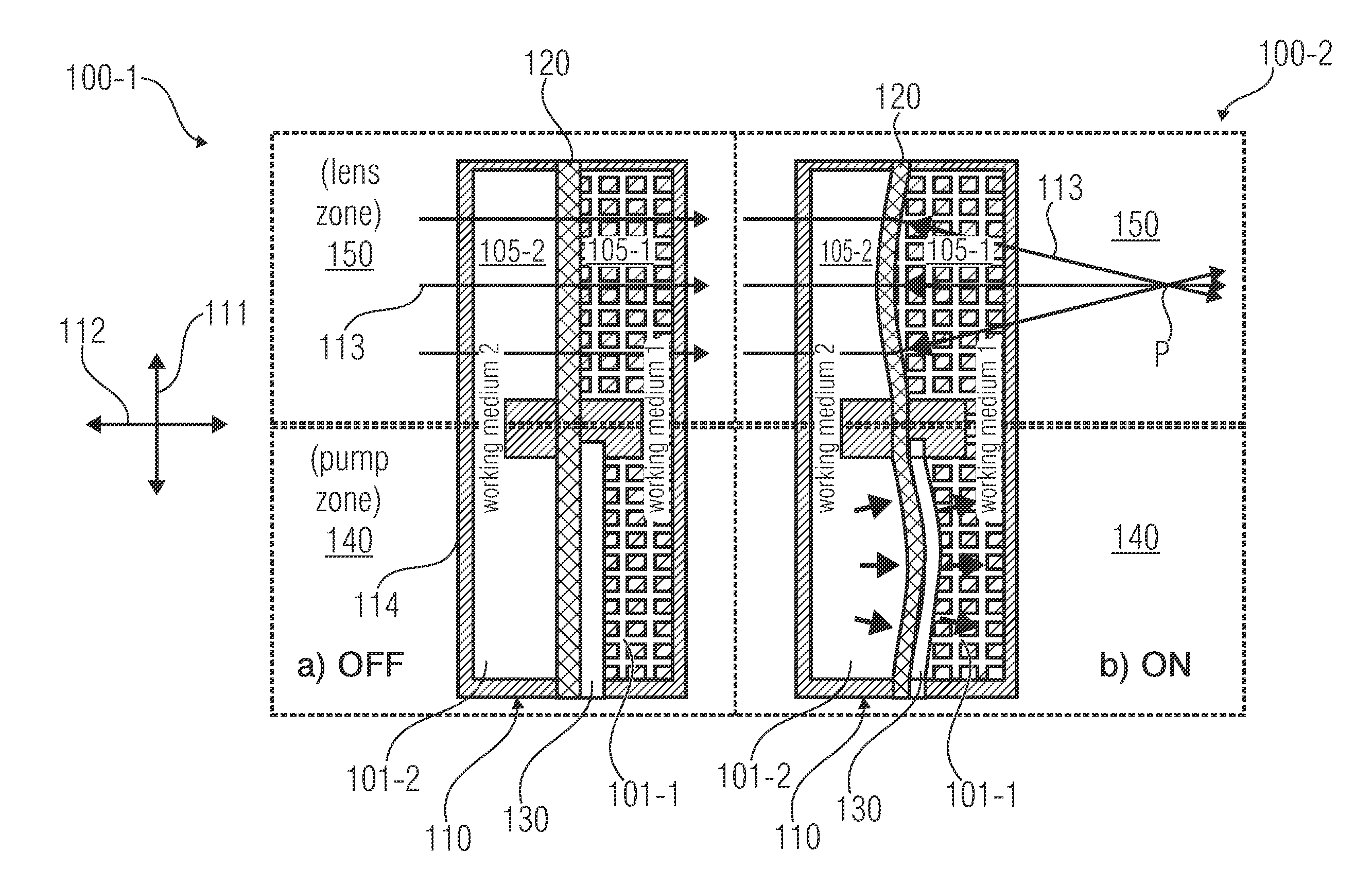
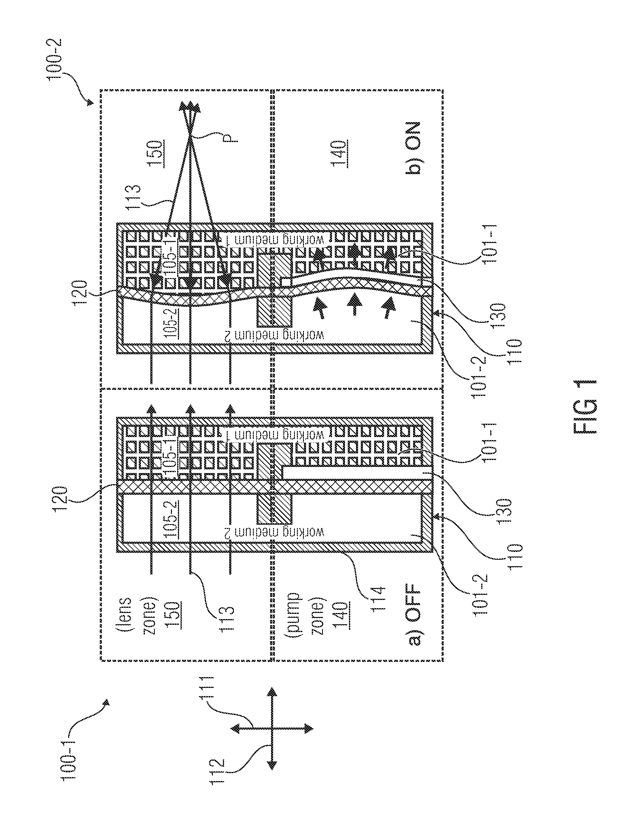
[0050]FIGS. 1a; 1b show a principle sketch of embodiments of a fluidic variable focal length optical lens 100-1; 100-2 with a pump zone and a lens zone in a deactivated state (‘off’-state) or an activated state (‘on’-state) of a deformator, respectively. As shown in FIGS. 1a; 1b, the respective fluidic variable focal length optical lens 100-1; 100-2 comprises a sealed housing 110 and a deformator 130. The sealed housing 110 comprises a first fluidic chamber 101-1 filled with a first fluidic medium 105-1 and a second fluidic chamber 101-2 filled with a second fluidic medium 105-2. Here, the first fluidic chamber 101-1 and the second fluidic chamber 101-2 are separated from each other by an elastic membrane 120 in a lens zone 150 and a combin...


PUM


Abstract

A fluidic variable focal length optical lens has a sealed housing having a first fluidic chamber filled with a first fluidic medium and a second fluidic chamber filled with a second fluidic medium, the first and the second fluidic chamber being separated from each other by an elastic membrane, wherein the first and the second fluidic medium have different refractive indices, and a deformator configured to deform the membrane laterally within a pump zone, thereby laterally displacing the first fluidic medium from the pump zone to a lens zone and the second fluidic medium from the lens zone to the pump zone, so that the membrane also deforms in the lens zone and changes a focal length of the lens zone along a normal direction.

Description

CROSS-REFERENCE TO RELATED APPLICATIONS[0001]This application is a continuation of copending International Application No. PCT / EP2010 / 060496, filed Jul. 20, 2010, which is incorporated herein by reference in its entirety.BACKGROUND OF THE INVENTION[0002]The present invention relates to a fluidic variable focal length optical lens and a method for manufacturing the same.[0003]There is an ever-increasing need for miniaturization and cost-effective solutions for lenses as part of imaging systems with either static or dynamic functions. In conventional optical imaging systems and cameras with auto-focus and zooming options, the physical positioning of a movable lens element to focus an image onto an image sensor or to change the overall magnification of the system is often realized by a manual operation of a bulky mechanical positioning system based on a complex arrangement of gears. The large physical dimension of a focusing and zooming system makes it difficult to place such optical z...

Claims


Application Information

Patent Timeline
IPC IPC(8): G02B3/14
CPCG02B26/004G02B3/14
Inventor COSTACHE, FLORENTASCHENK, HARALDBORNHORST, KIRSTINSCHIRRMANN, CHRISTIAN
Owner FRAUNHOFER GESELLSCHAFT ZUR FOERDERUNG DER ANGEWANDTEN FORSCHUNG EV
Learn More