
LED unit

Inactive Publication Date: 2013-05-23
FOXSEMICON INTEGRATED TECH INC
View PDF2 Cites 6 Cited by
  • Summary
  • Abstract
  • Description
  • Claims
  • Application Information

AI Technical Summary

Benefits of technology

The present disclosure relates to an LED unit that produces parallel light beams. The technical effect of the patent text is to provide an improved LED unit that can overcome the limitations of conventional lenses, which have limited light-converging capabilities. The LED unit includes a lens that produces parallel light beams, allowing for better lighting and longer distance travel of the light beams. The LED unit includes an LED module with a printed circuit board and an LED die mounted on it, and the lens is made from transparent materials such as PC or PMMA. The lens has a cavity open in the bottom face to receive the LED therein. The technical effect of the patent text is to provide an LED unit that produces parallel light beams with improved lighting capabilities.

Problems solved by technology

Conventionally, light directly output from the LED does not have a desirable pattern; therefore, a light-adjusting element, such as a lens, is used with the LED to modulate the light pattern thereof.
However, a typical lens generally has a limited light-converging capability; that is, light passing through the lens may not be effectively converged to a narrow beam.

Method used


Image

  • LED unit
  • LED unit
  • LED unit

Examples


Embodiment Construction

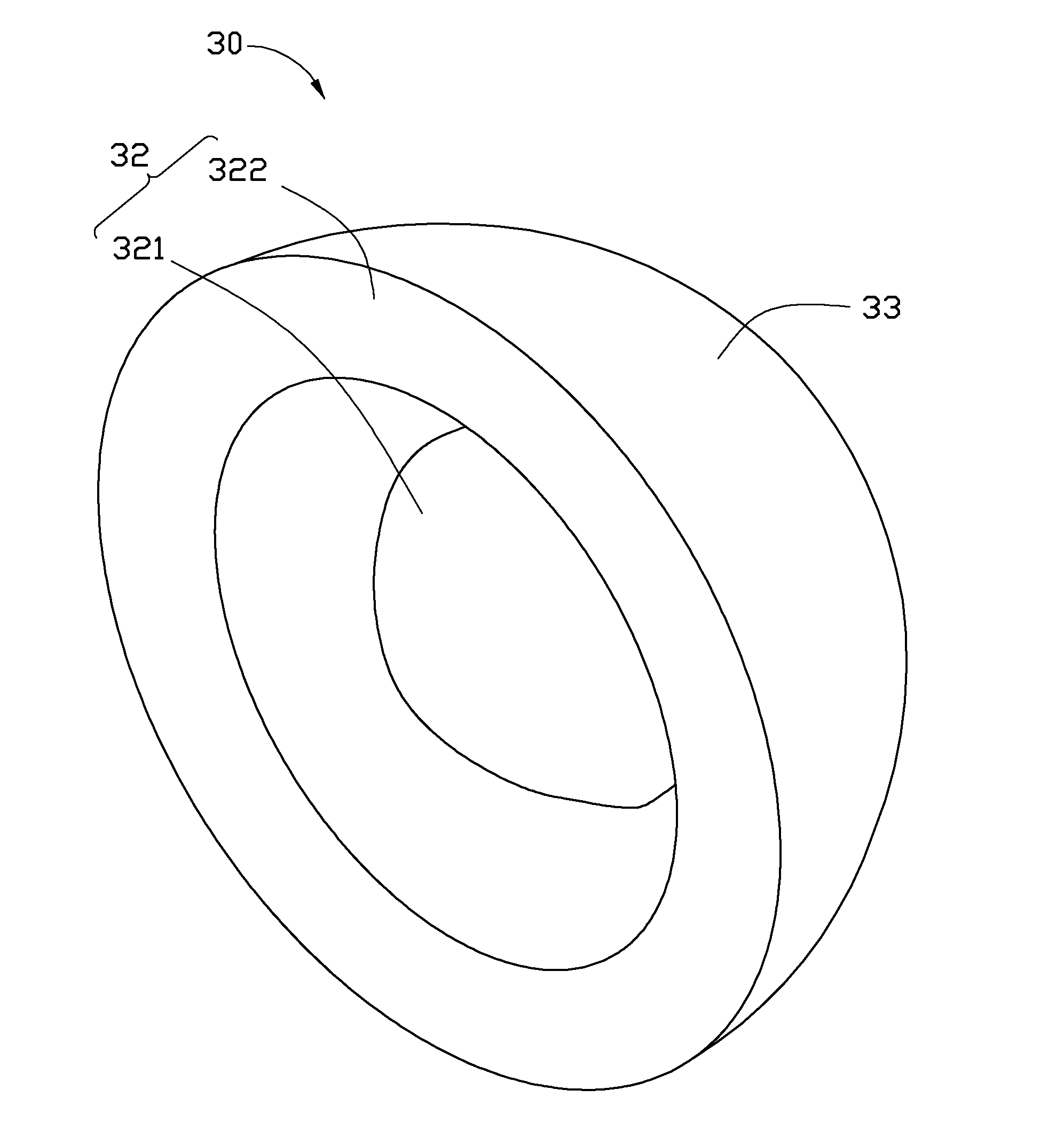
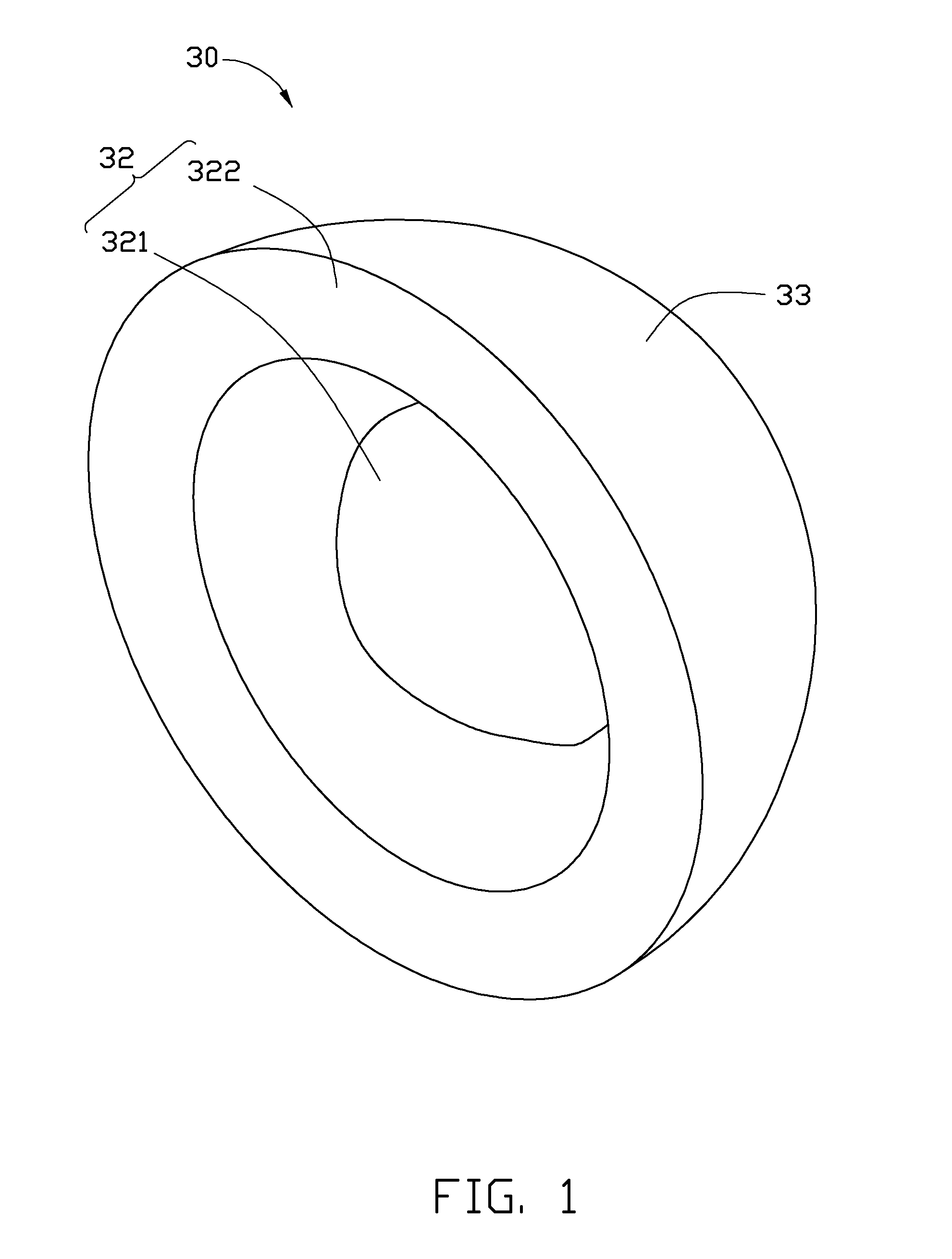
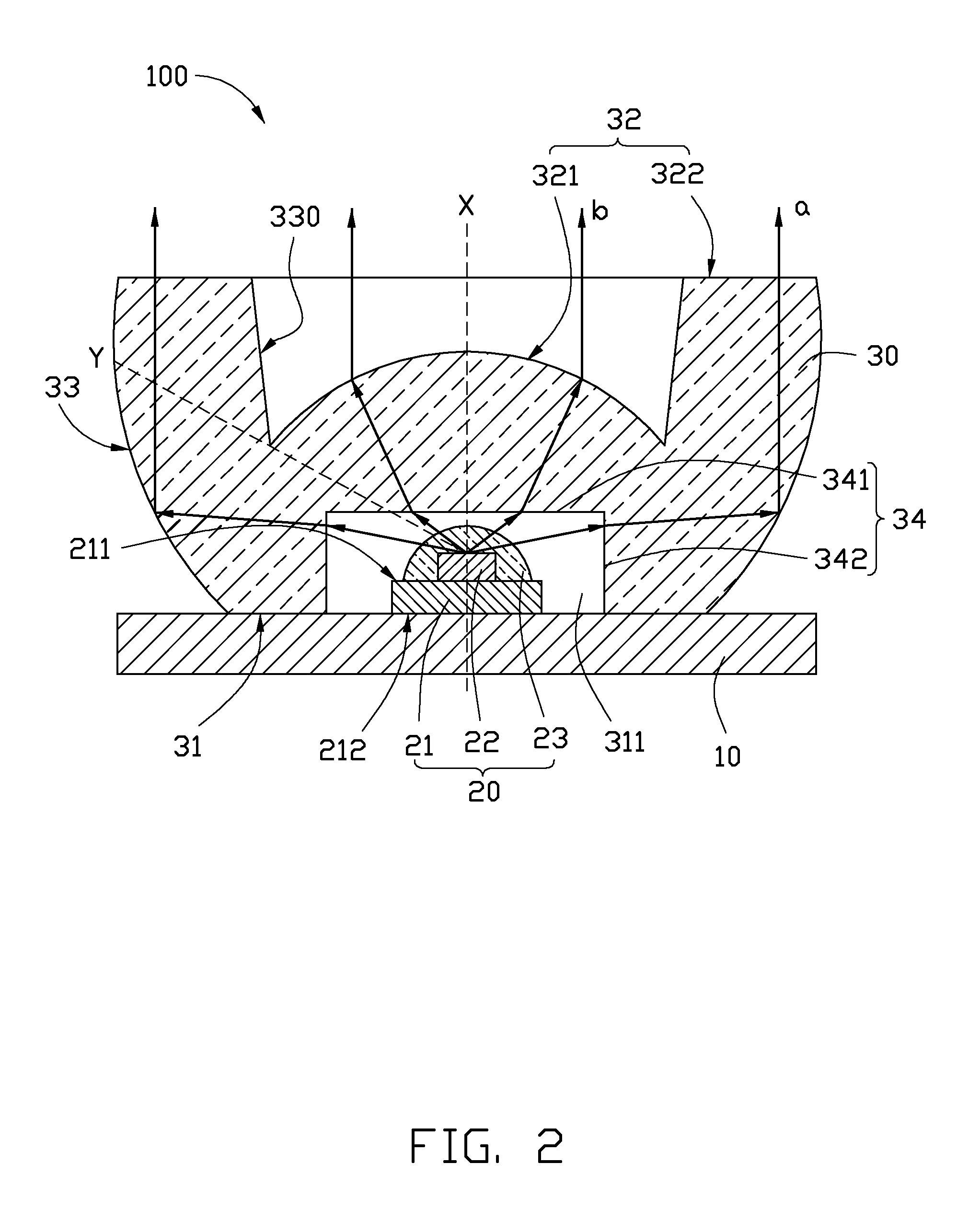
[0010]Referring to FIGS. 1 and 2, an LED unit 100 in accordance with an embodiment of the present disclosure is illustrated. The LED unit 100 includes an LED module and a lens 30 mounted on the LED module. The LED module includes a printed circuit board 10 and an LED (light emitting diode) 20 mounted on the printed circuit board 10. The printed circuit board 10 may be a MCPCB (Metal Core Printed Circuit Board), a CPCB (Ceramic Printed Circuit Board) or other types of printed circuit boards with good heat dissipation capabilities. The LED 20 includes a heat-conducting base 21, an LED die 22 mounted on a top face of the heat-conducting base 21, and an encapsulant 23 covering the LED die 22 and fixed to the top face 211 of the heat-conducting base 21. A bottom face 212 of the heat conducting base 21 of the LED 20 may be soldered on the printed circuit board 10 to conduct heat generated by the LED die 22 to the printed circuit board 10. In addition, the LED die 22 is electrically connec...


PUM


Abstract

A light emitting diode (LED) unit having a lens producing parallel light beams is disclosed. The LED unit comprises an LED; and a lens comprising a light incident face facing the LED, a light emergent face away from the LED, and a light reflecting face between the light incident face and the light emergent face; the light incident face comprises a first light incident face over the LED, and a second light incident face encircling the LED; and the light emergent face comprises a first light emergent face corresponding to the first light incident face, and a second light emergent face corresponding to the second light incident face, wherein the first light emergent face, relative to the first light incident face, is lower than the second light emergent face.

Description

BACKGROUND[0001]1. Technical Field[0002]The present disclosure relates to a light emitting diode (LED) unit and, more particularly, to an LED unit having a lens producing parallel light beams.[0003]2. Description of Related Art[0004]Light emitting diodes (LEDs) became available since the early 1960's, and because of their high light-emitting efficiency, have been increasingly used in a wide variety of applications in residential, traffic, commercial, and industrial locations. Conventionally, light directly output from the LED does not have a desirable pattern; therefore, a light-adjusting element, such as a lens, is used with the LED to modulate the light pattern thereof.[0005]However, a typical lens generally has a limited light-converging capability; that is, light passing through the lens may not be effectively converged to a narrow beam. As a result, light radiated from a typical lens may not travel long distances because of the spreading of the light beams.[0006]Therefore, an i...

Claims


Application Information

Patent Timeline
IPC IPC(8): F21V5/04F21V7/00
CPCF21V7/00F21V5/04F21V7/0091G02B19/0028G02B19/0061F21Y2115/10
Inventor CHANG, HSIU-PING
Owner FOXSEMICON INTEGRATED TECH INC
Features
  • Generate Ideas
  • Intellectual Property
  • Life Sciences
  • Materials
  • Tech Scout
  • Unparalleled Data Quality
  • Higher Quality Content
  • 60% Fewer Hallucinations
Learn More