Work implement control system

a control system and implement technology, applied in the direction of fluid couplings, rotary clutches, servomotors, etc., can solve the problems of less power efficiency and slower response in comparison to larger cross-sectional areas of control valves

Active Publication Date: 2013-05-23
CATERPILLAR INC
View PDF10 Cites 28 Cited by
  • Summary
  • Abstract
  • Description
  • Claims
  • Application Information

AI Technical Summary

Benefits of technology

[0004]A control system for a work implement on a machine is disclosed including a first hydraulic circuit, a second hydraulic circuit, and a controller. The first hydraulic circuit includes a hydraulic cylinder assembly, a pressurized fluid source, and a fluid tank. The hydraulic cylinder assembly includes a head end, a rod end, a cylinder, and a rod. The pressurized fluid source and the fluid tank are selectively connected to the head end or the rod end. The second hydraulic circuit includes a valve configured to receive a connection to tank signal, and selectively connect the head end or the rod end to the fluid tank. The controller is configured to generate the connection to tank signal.
[0005]A method of controlling a work implement on a machine is additionally disclosed. The work implement is operatively connected to a hydraulic cylinder assembly with a head end, and a rod end. The method includes directing fluid from the head end or the rod end to a tank through a first hydraulic circuit; commanding a work implement function; detecting a fluid pressure on the rod end; detecting a fluid pressure on the head end; generating a connection to tank cont

Problems solved by technology

Although smaller cross-sectional areas of control valves may allow better control during certain work conditions, they may be less power eff

Method used


Image

  • Work implement control system
  • Work implement control system
  • Work implement control system

Examples


first embodiment

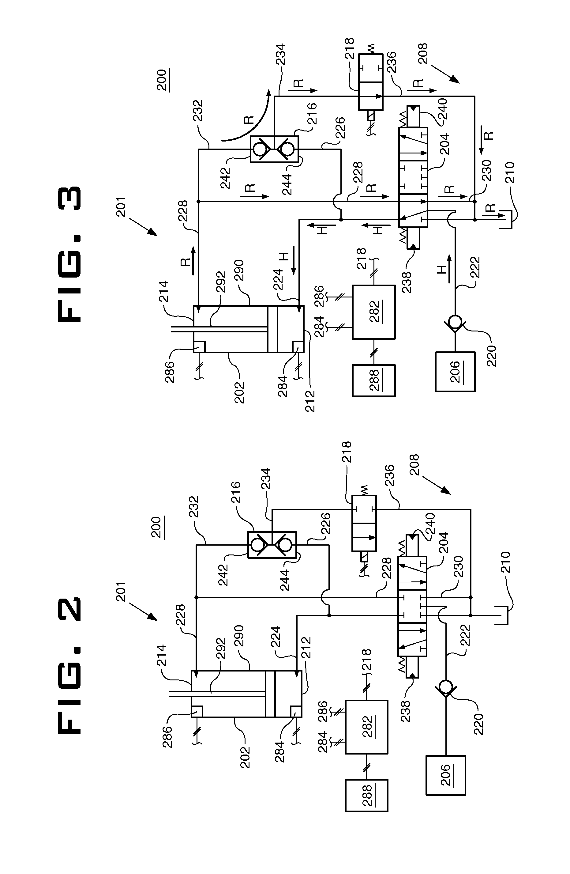
[0039]Referring now to FIGS. 2, 3, and 4, a work implement control system 200 is depicted. The system 200 includes a first hydraulic circuit 201, a second hydraulic circuit 208, and a controller 282.

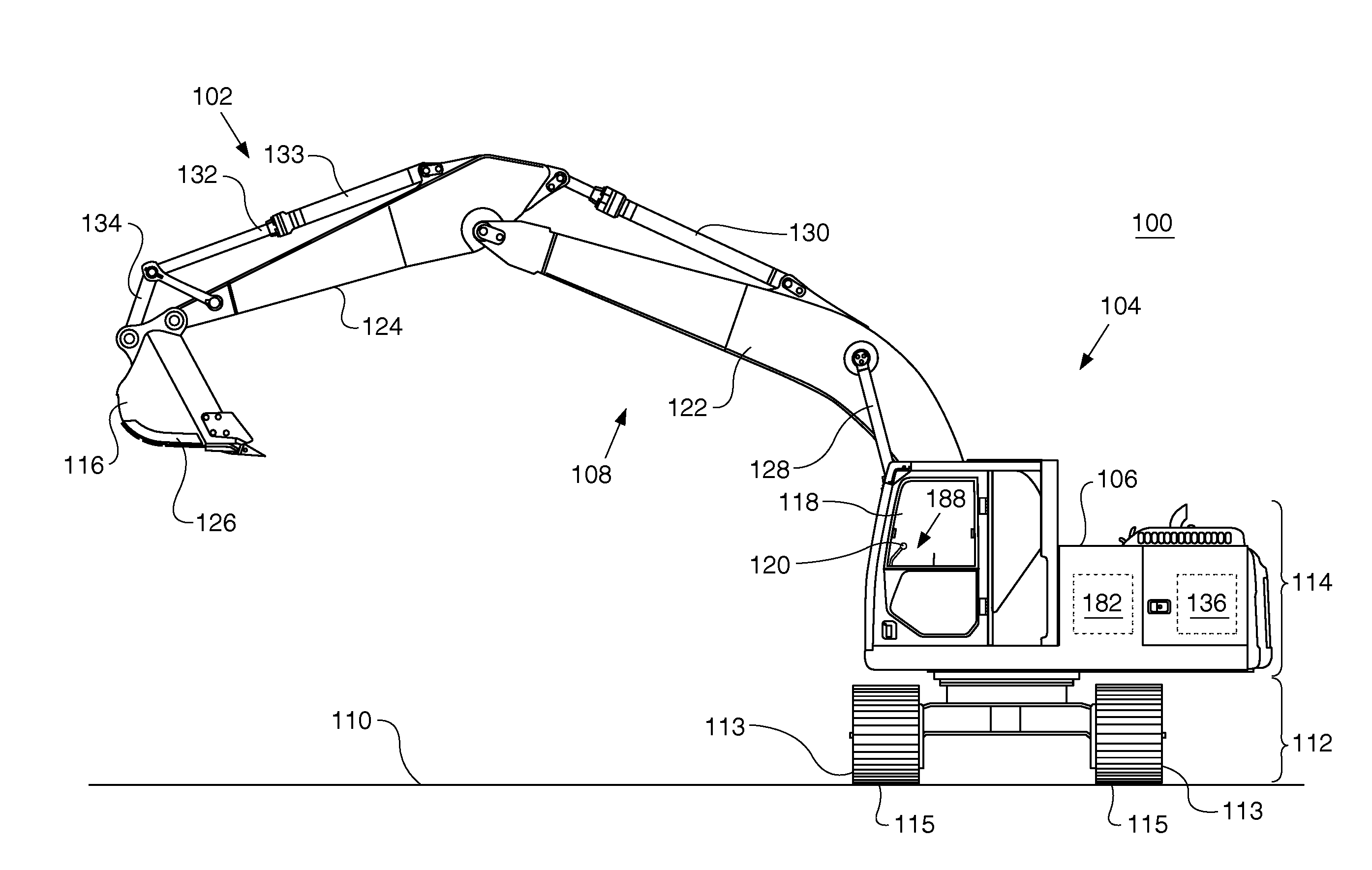
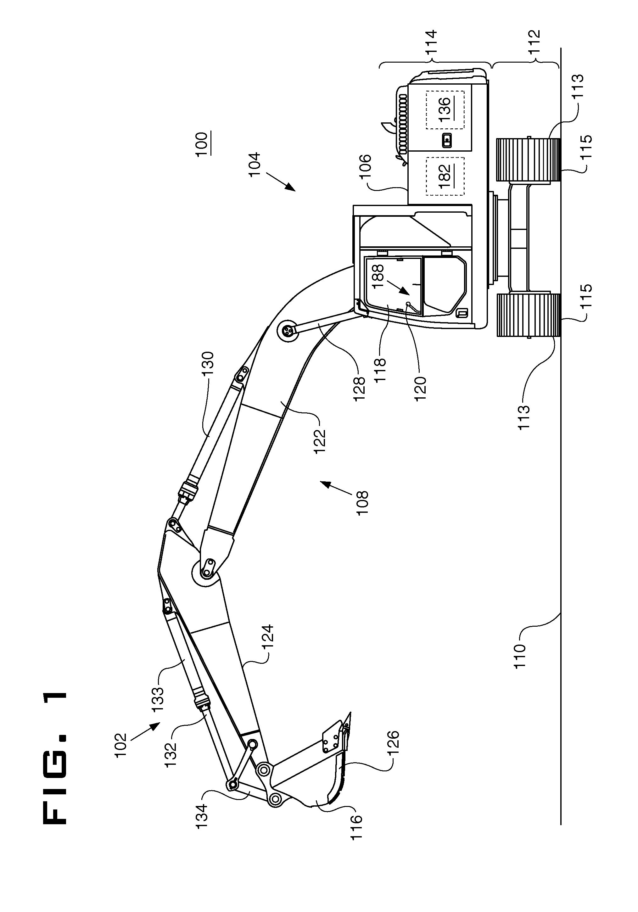
[0040]The first hydraulic circuit 201 includes a hydraulic cylinder assembly 202, a pressurized fluid source 206, and a fluid tank 210. The cylinder assembly 202 includes a head end 212 having a head end pressure, a rod end 214 having a rod end pressure, a cylinder 290, and a rod 292. The rod 292 is operably connected to the work implement 116. The fluid source 206 is selectively fluidly connected to the head end 212 and the rod end 214. The fluid tank 210 is selectively fluidly connected to the head end 212 and the rod end 214. When the fluid source 206 is fluidly connected to the head end 212, generally, the fluid tank 210 is fluidly connected to the rod end 214. Conversely, when the fluid source 206 is fluidly connected to the rod end 214, generally, the fluid tank 210 is fluidly conn...

second embodiment

[0075]Referring now to FIGS. 5, 6, and 7, the work implement control system 300 is depicted. The system 300 includes a first hydraulic circuit 301, a second hydraulic circuit 308, and a controller 382.

[0076]The first hydraulic circuit 301 includes a hydraulic cylinder assembly 302, a pressurized fluid source 306, and a fluid tank 310. The cylinder assembly 302 includes a head end 312 having a head end pressure, a rod end 314 having a rod end pressure, a cylinder 390, and a rod 392. The rod 392 is operably connected to the work implement 116. The fluid source 306 is selectively fluidly connected to the head end 312 and the rod end 314. The fluid tank 310 is selectively fluidly connected to the head end 312 and the rod end 314. When the fluid source 306 is fluidly connected to the head end 312, generally, the fluid tank 310 is fluidly connected to the rod end 314. Conversely, when the fluid source 306 is fluidly connected to the rod end 314, generally, the fluid tank 310 is fluidly co...


PUM


Abstract

A control system for a work implement on a machine is disclosed including a first hydraulic circuit, a second hydraulic circuit, and a controller. The first hydraulic circuit includes a hydraulic cylinder assembly, a pressurized fluid source, and a fluid tank. The hydraulic cylinder assembly includes a head end, a rod end, a cylinder, and a rod. The pressurized fluid source and the fluid tank are selectively connected to the head end or the rod end. The second hydraulic circuit includes a valve configured to receive a connection to tank signal and selectively connect the head end or the rod end to the fluid tank. The controller is configured to generate the connection to tank signal.

Description

TECHNICAL FIELD[0001]The present disclosure relates generally to work implement control systems. Specifically, the disclosure relates to an implement control system including a hydraulic circuit and a hydraulic cylinder assembly.BACKGROUND[0002]Machines with work implement systems actuated with hydraulic circuits and hydraulic cylinder assemblies may size hydraulic control valves to allow operators more control when work implements are subject to over-running loads. This sizing of control valves may also allow fine control of work implement movements during operation. Although smaller cross-sectional areas of control valves may allow better control during certain work conditions, they may be less power efficient and slower to respond in comparison to larger cross-sectional areas of control valves, when work implements encounter resistive loads.[0003]United States Patent Application Publication US 201010024410 A1 filed by Brickner discloses a hydraulic system for a machine. The hydra...

Claims


Application Information

Patent Timeline
IPC IPC(8): E02F9/22F15B13/02E02F9/20E02F3/36E02F1/00
CPCF15B11/044F15B2211/3052F15B2211/30565F15B2211/31558F15B2211/353F15B2211/6313E02F9/2217F15B2211/7053F15B2211/761E02F9/0883E02F9/2029E02F9/2095E02F9/2203F15B2211/665
Inventor GABIBULAYEV, MAGOMED O.
Owner CATERPILLAR INC
Why Eureka
Try Eureka