Autonomous mobile body and control method of same

a mobile body and control method technology, applied in the direction of process and machine control, distance measurement, instruments, etc., can solve the problem that the orientation of the mobile body has not been considered, and achieve the effect of avoiding obstacles carefully, facilitating the combination of potential membership functions and facilitating the generation of respective amounts of control

Active Publication Date: 2013-05-23
MURATA MASCH LTD
View PDF22 Cites 13 Cited by
  • Summary
  • Abstract
  • Description
  • Claims
  • Application Information

AI Technical Summary

Benefits of technology

[0009]a potential generator for generating a translational potential of the mobile body and a rotational potential of the mobile body for avoiding interference with the obstacle, based on the distance from the autonomous mobile body to the obstacle at each directional angle;
[0022]Preferably, the control amount generator derives the amount of translational control and the amount of rotational control independently. According to this configuration, respective amounts of control are easily generated by disregarding interaction between translation and rotation. Combining the generated amounts of control most preferably involves summing the amount of translational control and the amount of rotational control. According to this configuration, the movement mechanism is easily driven by the summation of amounts of control.

Problems solved by technology

Obstacles occur in areas other than walls and pillars such as passageways and the like through which the mobile body is capable of passing, although those areas are not always wide enough.
However, since most research to date has involved searching for a movement path using models approximating a mobile body to a circle, no consideration whatsoever has been given to changing the orientation of the mobile body.

Method used


Image

  • Autonomous mobile body and control method of same
  • Autonomous mobile body and control method of same
  • Autonomous mobile body and control method of same

Examples


embodiment

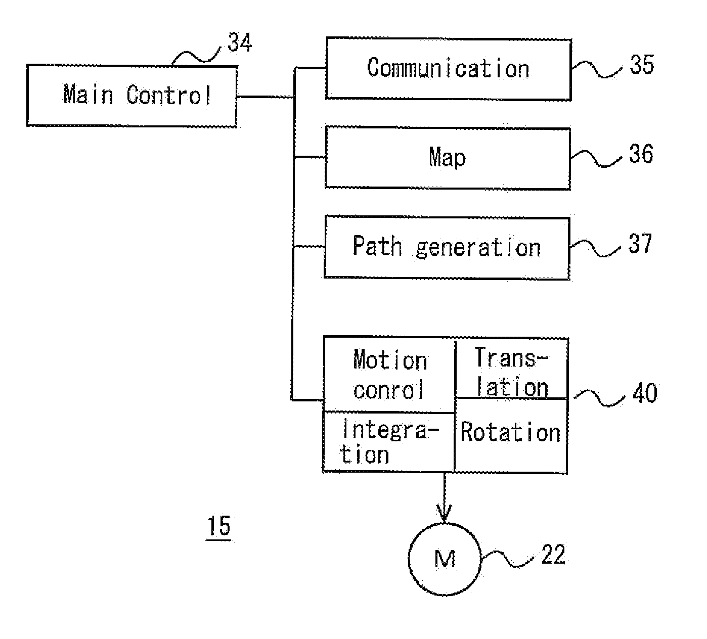
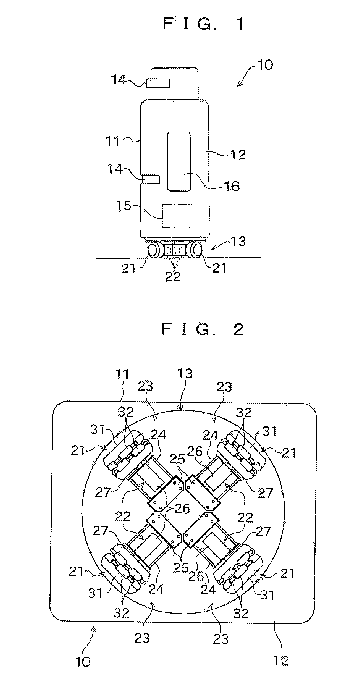
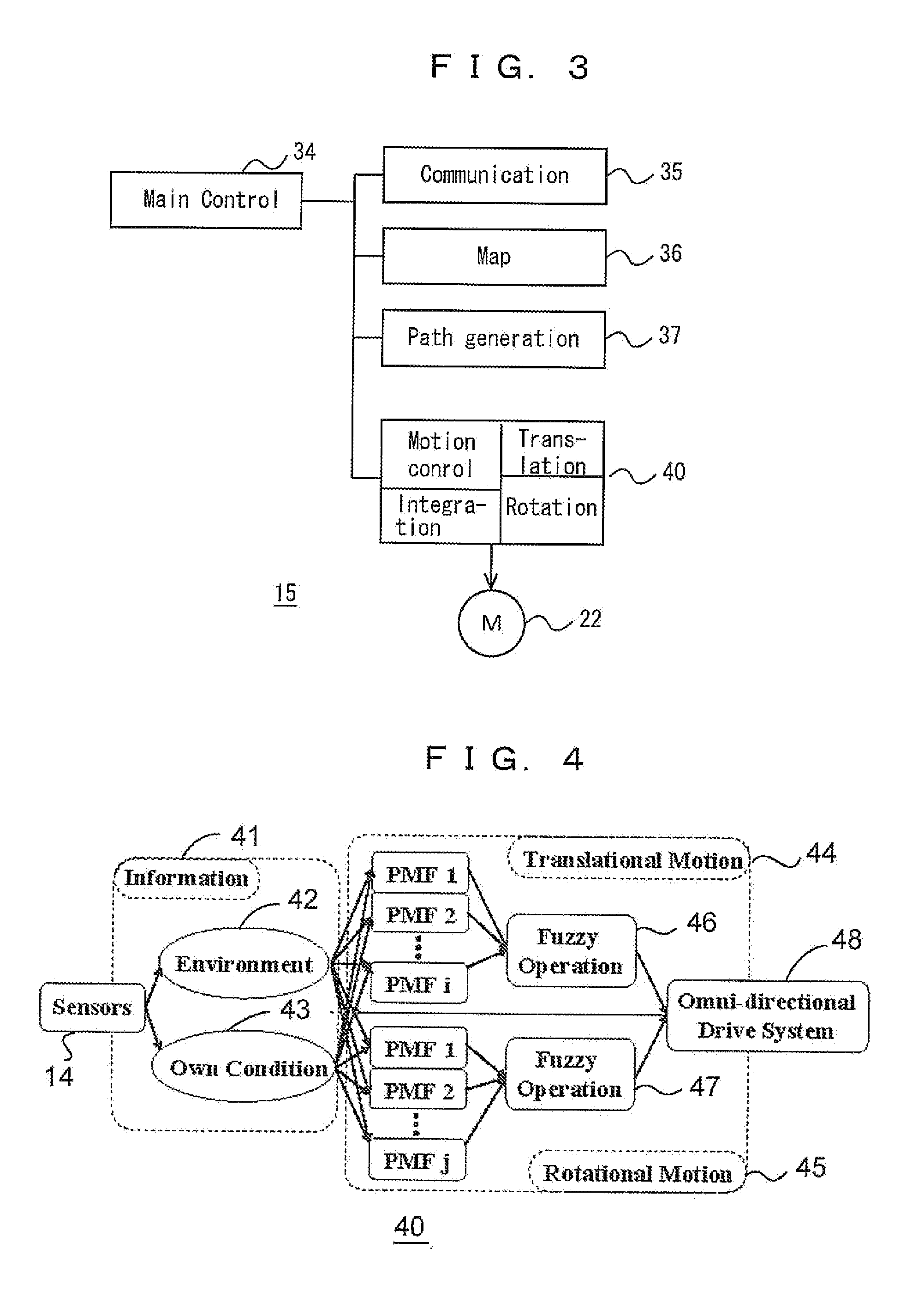
[0047]FIGS. 1 to 22 show an autonomous mobile robot 10 and control thereof according to an embodiment. Referring to FIG. 1, the robot 10 includes a platform vehicle 13 provided with an omni-directional movement mechanism, with the platform vehicle 13 supporting an upper part 12 serving as an upper body. The upper part 12 is provided with a pair of, for example, laser range finders 14, each of which is attached at a different height. A stereoscopic device such as a stereo camera, light sources and cameras for space coding, or the like may be provided instead of the laser range finders 14. With the above configuration, the robot 10 acquires, at a number of heights, information indicating the distance between the robot and obstacles for each of predetermined directional angles, and outputs the distance information. The robot 10 may recognize its current position and orientation by being equipped with GPS or the like (not shown), or may alternatively recognize its current position and o...


PUM


Abstract

An autonomous mobile body is configured to flexibly avoid obstacles. The mobile body has a movement mechanism configured to translate in a horizontal plane and rotate around a vertical axis, and the distance to an obstacle is derived for each directional angle using an obstacle sensor. A translational potential of the mobile body and a rotational potential of the mobile body for avoiding interference with the obstacle are generated, based on the distance from the autonomous mobile body to the obstacle at each directional angle. An amount of control relating to a translational direction and a translational velocity of the mobile body and an amount of control relating to a rotational direction and an angular velocity of the mobile body are generated based on the generated potentials, and the movement mechanism is driven.

Description

TECHNICAL FIELD [0001]The present invention relates to autonomous mobile bodies such as robots and auto-guided vehicles, and to controlling the movement thereof.BACKGROUND ART[0002]Mobile bodies such as robots that provide various services in real environments where there are people such as offices and factories are being developed, with development of such robots being premised on the robots moving autonomously to a destination while avoiding obstacles. Non-patent Literature 1 discloses an artificial potential field approach regarding obstacle avoidance. According to this artificial potential field approach, an attractive potential for the destination and repulsive potentials for obstacles to be avoided are generated, and control is implemented according to the gradients of the potential field on which these potentials are superimposed. Traction motors are driven in accordance with this control, and the mobile body arrives at its destination while avoiding obstacles.[0003]When avoi...

Claims


Application Information

Patent Timeline
Patent Type & Authority Applications(United States)
IPC IPC(8): G05D1/02B25J13/00B25J5/00
CPCB25J5/007G05D1/0212G05D1/024Y10S901/01B25J13/00G05D1/021B25J5/00G05D1/0238G05D1/02
Inventor TAKAHASHI, MASAKISUZUKI, TAKAFUMIMORIGUCHI, TOSHIKI
Owner MURATA MASCH LTD
Why Eureka
Try Eureka