Joint between bed frame and fabric member

Inactive Publication Date: 2013-05-30
CHENG PAO HSIEN
View PDF13 Cites 9 Cited by
  • Summary
  • Abstract
  • Description
  • Claims
  • Application Information

AI Technical Summary

Benefits of technology

[0007]Therefore it is a primary object of the present invention to provide a joint between a bed frame and a fabric member, especially to a novel joint between a bed frame and

Problems solved by technology

And each positioning block is unable to be released from the assembly space axially because tha

Method used


Image

  • Joint between bed frame and fabric member
  • Joint between bed frame and fabric member
  • Joint between bed frame and fabric member

Examples


Example

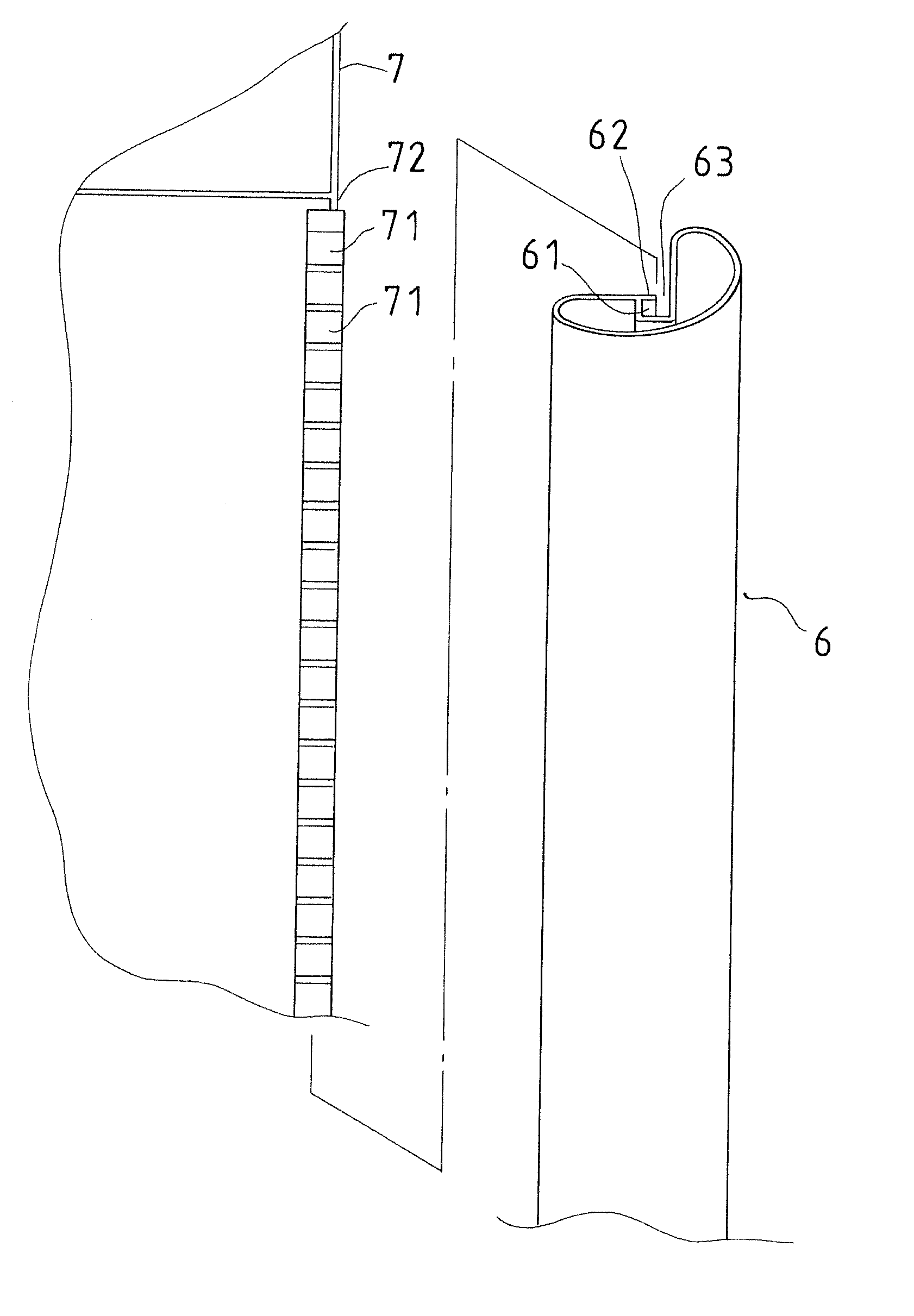
[0018]Refer to FIG. 5 and FIG. 6, explosive views of a joint of a bed frame from different viewing angles are revealed.

[0019]The bed frame includes a plurality of vertical tubes 6 each of which includes an assembly space 61 at one side, an extending portion 62 arranged at one side of the assembly space 61 along an axis of the assembly space 61. Due to the disposition of the extending portion 62, the assembly space 61 has a narrow opening 63 beside the extending portion 62.

[0020]A fabric member 7 is disposed with a plurality of positioning blocks 71 corresponding to the assembly space 61 of each vertical tube 6. The maximum outside diameter of each positioning block 71 is larger than the width of the narrow opening 63 of the vertical tube 6. Each positioning block 71 is fixed on the fabric member 7 by a connection portion 72 connected to the fabric member 7. Each connection portion 72 is corresponding to one vertical tube 6. The thickness of the connection portion 72 is smaller than ...


PUM


Abstract

A joint between a bed frame and a fabric member is revealed. The bed frame includes a plurality of vertical tubes each of which includes an assembly space with a narrow opening. A connection portion connects a plurality of positioning blocks to the fabric member and the positioning blocks are corresponding to the assembly space of each vertical tube. Thereby positioning blocks are mounted into the assembly space from one end of the vertical tube and the connection portion is extending outward through the narrow opening of the vertical tube. Each positioning block is unable to be released from the assembly space axially due to that the outside diameter of the positioning block is larger than the width of the narrow opening. Thus the fabric member and each vertical tube are connected firmly.

Description

BACKGROUND OF THE INVENTION[0001]1. Field of the Invention[0002]The present invention relates to a joint between a bed frame and a fabric member, especially to a joint between a bed frame and a fabric member in which the fabric member is assembled with and fixed around the bed frame quickly and easily so as to define a surrounding wall around the bed frame.[0003]2. Description of Related Art[0004]A conventional bed includes a bed frame and a fabric member wrapped around the bed frame to form a surrounding wall. Generally, a joint between the bed frame and the fabric member is as shown in FIG. 1 and FIG. 2. A plurality of circular columns 11 is formed on a fabric member 1 by sewing. Then each upright tube 21 of a bed frame 2 is inserted into the circular column 11. However, the circular column 11 is formed on the fabric member 1 by sewing. Once there are some errors happened during the sewing and the inside diameter of the circular column 11 is not within a standard deviation, the up...

Claims


Application Information

Patent Timeline
IPC IPC(8): A47C19/02
CPCA47D7/00A47D13/066A47D13/063
Inventor CHENG, PAO-HSIEN
Owner CHENG PAO HSIEN
Why Eureka
Try Eureka