Blended flow air cycle system for environmental control

Active Publication Date: 2013-05-30
HAMILTON SUNDSTRAND CORP
View PDF14 Cites 60 Cited by
  • Summary
  • Abstract
  • Description
  • Claims
  • Application Information

AI Technical Summary

Problems solved by technology

This pre-conditioning of the bleed air for the distribution system wastes the energy provided by the engine in compressing the air for extraction at the bleed port.
This waste of energy is manifested in increased fuel burn required to maintain the desired thrust while also providing t

Method used


Image

  • Blended flow air cycle system for environmental control
  • Blended flow air cycle system for environmental control
  • Blended flow air cycle system for environmental control

Examples


Embodiment Construction

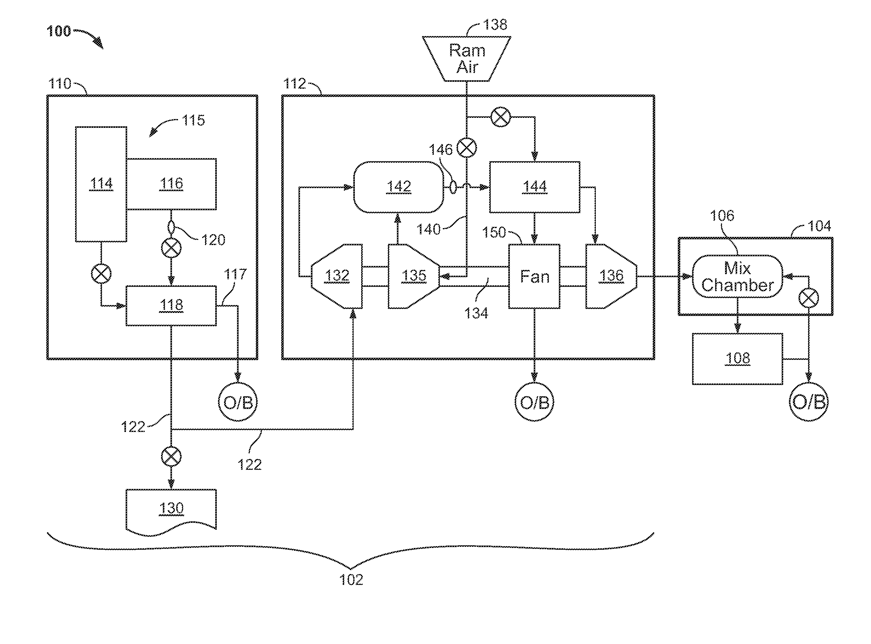
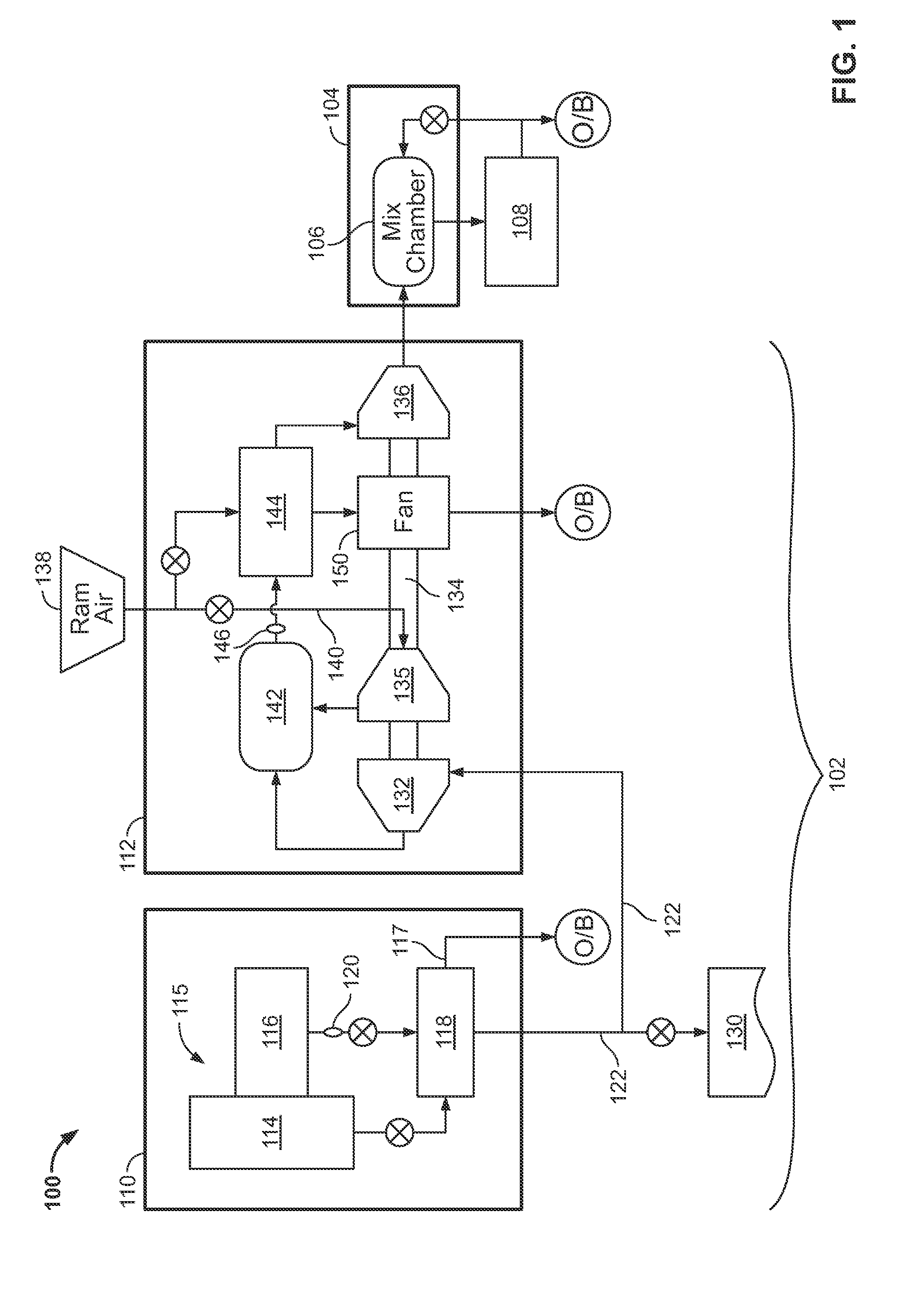
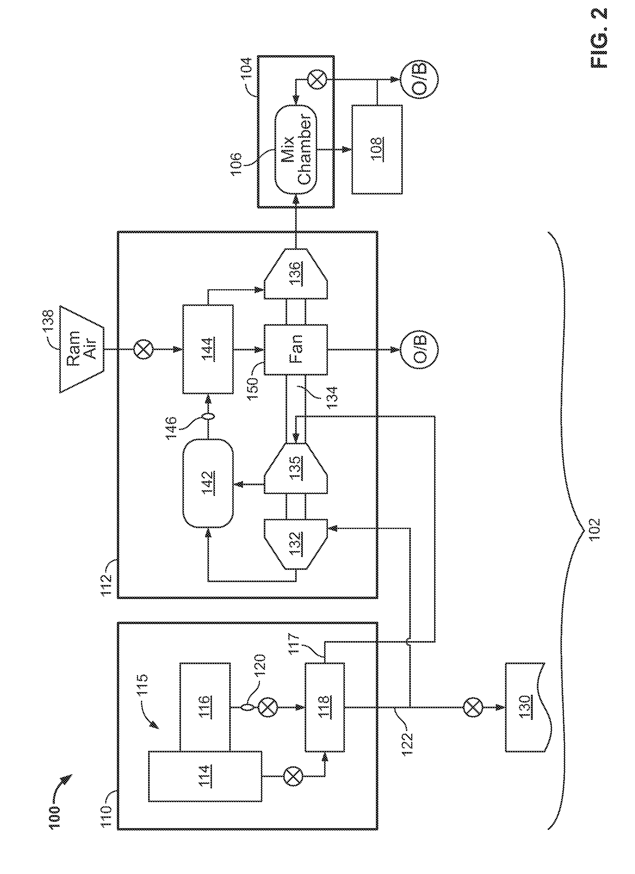
[0009]Embodiments of the present invention that are described in greater detail below may improve the efficiency of engine bleed air extraction by utilizing more of the bleed air energy contained in the bleed air stream coming out of a compressor section of a turbine engine than in conventional systems. Typically, all of the cabin / flight deck air is provided by the engine bleed system. In embodiments disclosed herein, only a portion of the required cabin air is provided through this method. The remaining portion of the cabin / flight deck air is provided by either ram air extraction at prevailing static conditions of the atmosphere, or from lower pressure fan air extraction, depending upon which embodiment of the invention is employed. However, two air streams at different pressures cannot be mixed without some pressure reduction in the higher energy stream (bleed air) or pressure increase in the lower energy stream (ram air). In embodiments disclosed herein, excess pressure in the bl...


PUM


Abstract

An aircraft air provision system includes a power turbine that receives bleed air at a first pressure and provides rotational energy to a shaft and outputs output air at an intermediate pressure. The system also includes a compressor coupled to the shaft that receives input air at a second pressure that is lower than the first pressure and outputs compressed air having a pressure equal to the intermediate pressure and a mix chamber coupled to outputs of both the power turbine and the compressor where the output air and the compressed air are mixed. The system also includes a cooling turbine coupled to the shaft and that is in fluid communication with an output of the mix chamber.

Description

BACKGROUND OF THE INVENTION[0001]The subject matter disclosed herein relates to environmental control systems and, in particular, to environmental control systems in an aircraft.[0002]Aircraft have power systems that are comprised of several components, such as an engine, an environmental control system and a thermal management system. These systems are designed relatively independently from each other with power being transferred from one system to another.[0003]The environmental control system (ECS) supplies pressurized air to the cabin and flight deck of an aircraft for both comfort and pressurization. The air is drawn from either or both the compressor stage of the engine (a bleed air system) or directly from exterior air (ram air system). In more detail, bleed air is extracted from the engine core at a pre-defined stage location in the engine compressor region. Frequently, this bleed air is delivered to the aircraft at temperature and pressure states well above what can be safe...

Claims


Application Information

Patent Timeline
IPC IPC(8): F25B9/00
CPCB64D13/08Y02T50/56B64D2013/0618Y02T50/50B64D13/02B64D2013/0648B64D2013/0688F25B9/004F25B9/10
Inventor SQUIER, STEVEN E.
Owner HAMILTON SUNDSTRAND CORP
Why Eureka
Try Eureka