Pedal effort adjusting apparatus for accelerator pedal

a technology of pedal effort and adjustment apparatus, which is applied in the direction of mechanical control devices, process and machine control, instruments, etc., can solve the problems of incompatibility of acceleration pedal devices, driver difficulty in sufficiently falling the operation of acceleration pedals, and pedals feel more, and achieves the effect of simple operation

Inactive Publication Date: 2013-05-30
HYUNDAI MOTOR CO LTD +1
View PDF5 Cites 4 Cited by
  • Summary
  • Abstract
  • Description
  • Claims
  • Application Information

AI Technical Summary

Benefits of technology

[0011]Various aspects of the present invention provide for a pedal effort adjusting apparatus of an acceleration pedal that can sufficiently satisfy the law of safety about a pedal effort a...

Problems solved by technology

Since the larger the pedal effort, the more the force applied to the pedal arm 2 by a driver increases, the driver operating the acceleration pedal feels more tired, whereas when the pedal effort is small, the driver has difficulty in sufficiently felling the operation of the acceleration pedal, such that automobile manufacturers set the characteristics of a pedal ef...

Method used


Image

  • Pedal effort adjusting apparatus for accelerator pedal
  • Pedal effort adjusting apparatus for accelerator pedal
  • Pedal effort adjusting apparatus for accelerator pedal

Examples


Embodiment Construction

[0030]Reference will now be made in detail to various embodiments of the present invention(s), examples of which are illustrated in the accompanying drawings and described below. While the invention(s) will be described in conjunction with exemplary embodiments, it will be understood that present description is not intended to limit the invention(s) to those exemplary embodiments. On the contrary, the invention(s) is / are intended to cover not only the exemplary embodiments, but also various alternatives, modifications, equivalents and other embodiments, which may be included within the spirit and scope of the invention as defined by the appended claims.

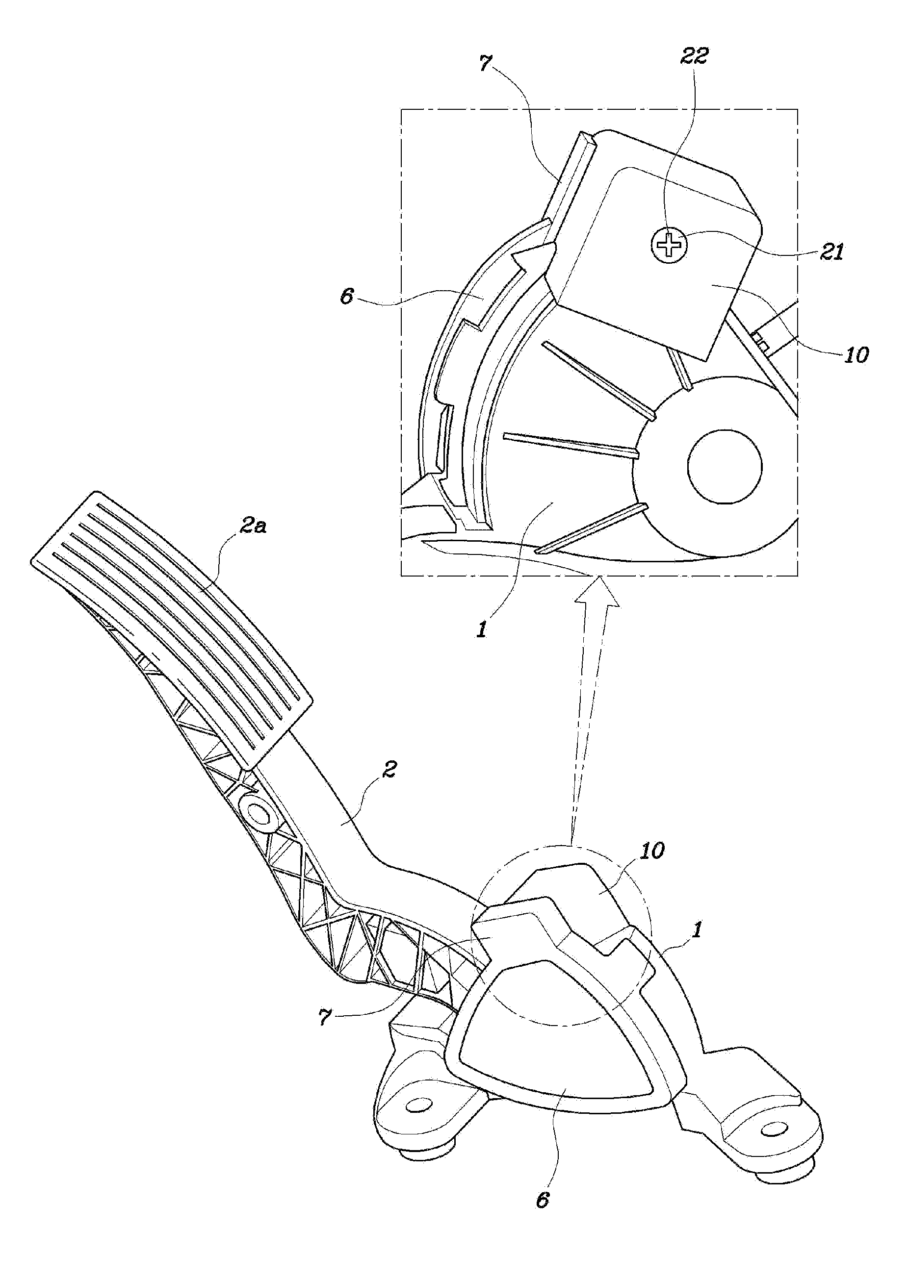
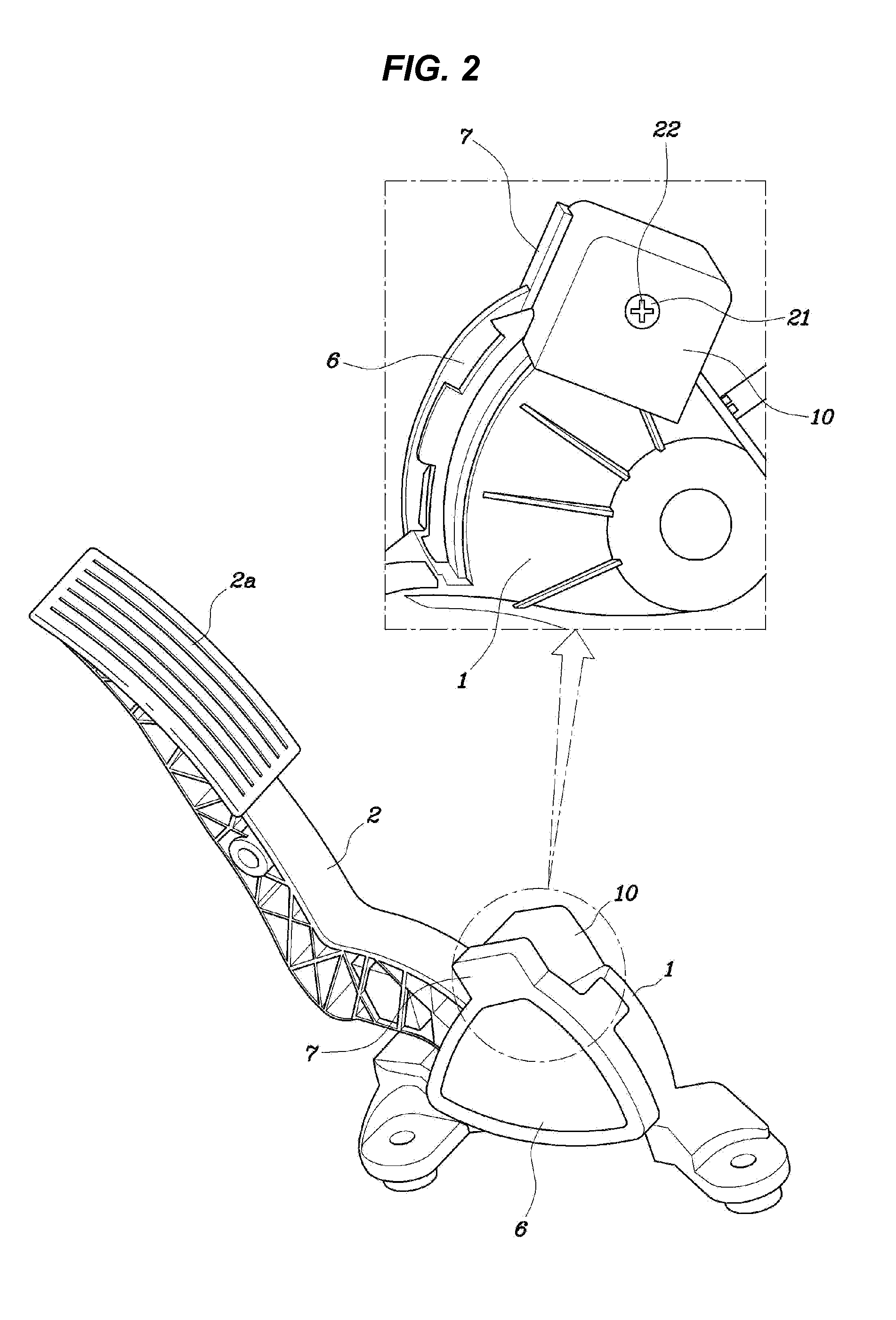
[0031]An acceleration pedal of a vehicle includes, as shown in FIGS. 2 to 6, a pedal arm housing 1 fixed to the dash panel under a driver seat, a pedal arm 2 having an end equipped with a pedal 2a and the other end inserted in the pedal arm 1 to be rotatable about a hinge shaft 2b with respect to the pedal arm housing 1, a spring plat...


PUM


Abstract

A pedal effort adjusting apparatus of an acceleration pedal allows adjustment of the elastic force of an elastic member by moving a carrier with rotation of a rotary cam and to easily adjust a pedal effort of a pedal arm, if necessary.

Description

CROSS-REFERENCE TO RELATED APPLICATION[0001]The present application claims priority of Korean Patent Application Number 10-2011-0123340 filed Nov. 24, 2011, the entire contents of which application is incorporated herein for all purposes by this reference.BACKGROUND OF INVENTION[0002]1. Field of Invention[0003]The present invention relates to a pedal effort adjusting apparatus of an accelerator pedal that can adjust a pedal effort of an accelerator pedal by simple operation of a user.[0004]2. Description of Related Art[0005]An acceleration pedal device of the related art includes, as shown in FIG. 1, a pedal arm housing 1 fixed to the dash panel under a driver seat, a pedal arm 2 having an end equipped with a pedal 2a and the other end inserted in the pedal arm 1 to be rotatable with respect to the pedal arm housing 1, a spring plate 3 coupled to the end of the pedal arm 2 disposed in the pedal arm housing 1, a friction shoe 4 coupled to the pedal arm 2 disposed in the pedal arm hou...

Claims


Application Information

Patent Timeline
IPC IPC(8): F16H53/02
CPCB60K26/02Y10T74/2101G05G1/40G05G1/30B60K26/00
Inventor KIM, EUN SIKLEE, SUNG IIMIN, JEONG SEONCHO, YANG RAEKIM, SUN GEUN
Owner HYUNDAI MOTOR CO LTD
Why Eureka
Try Eureka