Multi-part insert

Active Publication Date: 2013-05-30
ZEPHYROS INC
View PDF10 Cites 40 Cited by
  • Summary
  • Abstract
  • Description
  • Claims
  • Application Information

AI Technical Summary

Benefits of technology

[0008]One unique aspect of the present invention envisions an insert with multiple carrier portions that when attached and/or combined include an internal channel along the longitudinal axis so that components, devices, fluids, or a combination thereof may pass at least a portion of the way through the insert. The portions of the channel are integrally made in the carrier portions so that when the carriers are combined the insert includes an integral channel, thus, eliminating the need for an additional tube being used with the insert.
[0009]Another unique aspect of the present invention envisions increased flexibility with the size (i.e. cross-sectional dimension and/or length) of the channel. The present invention will allow for channels to be included in parts with smaller cross-sectional dimensions and parts with an increased length

Problems solved by technology

One disadvantage faced by known inserts is that as the inserts become longer and longer (i.e., longer than 12 cm) it is no longer feasible to hollow out parts of the carrier to accommodate components, devices, fluids, or a combination thereof.
In some instances the length of the part is less than 12 cm, but the cross-section of the part is small and due to the small cross-section the carrier cannot be hollowed out.
Another disadvantage faced by known inserts is that once the reinforcement material is cured in the cavity the reinforcement material becomes increasingly difficult to core due to the hardness of the reinforcement material, the geometry of the insert, the geometry of the cavity, or a combination thereof.
However, adding a tube alongside of the insert may be time consuming and/or difficult due to

Method used


Image

  • Multi-part insert
  • Multi-part insert
  • Multi-part insert

Examples


Example

[0017]The following description of the preferred embodiment(s) is merely exemplary in nature and is in no way intended to limit the invention, its application, or uses. This application is related to and claims the benefit of the filing date of U.S. Provisional Application Ser. No. 61 / 564,490, filed on Nov. 29, 2011, the contents of this application being incorporated by reference herein for all purposes.

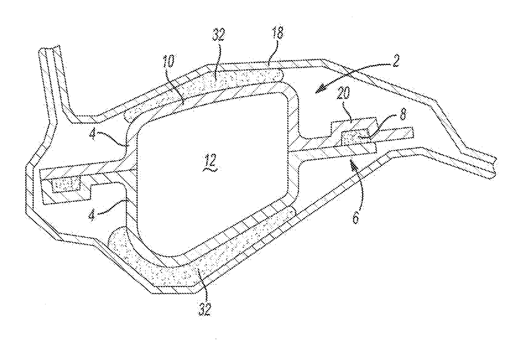
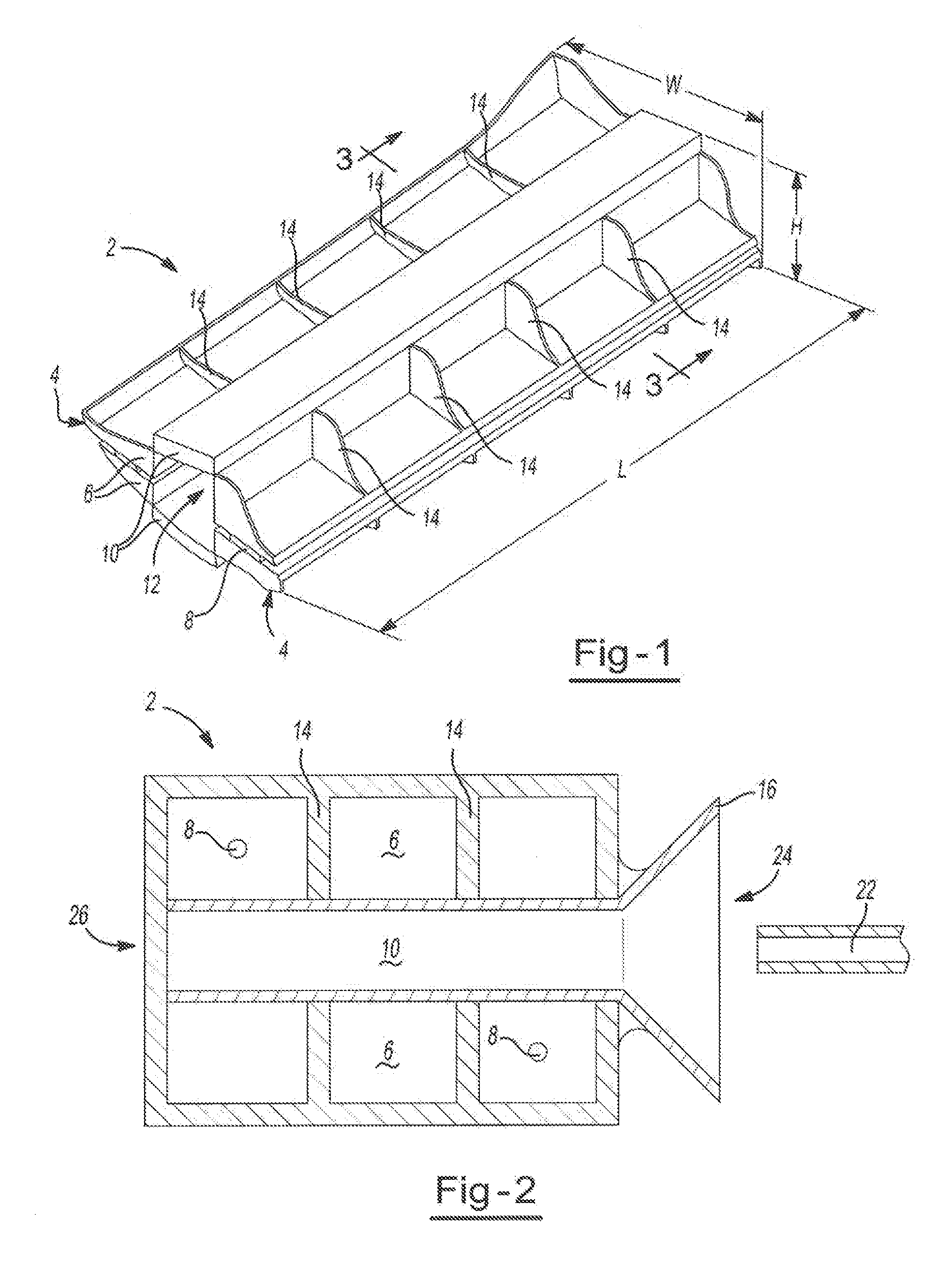
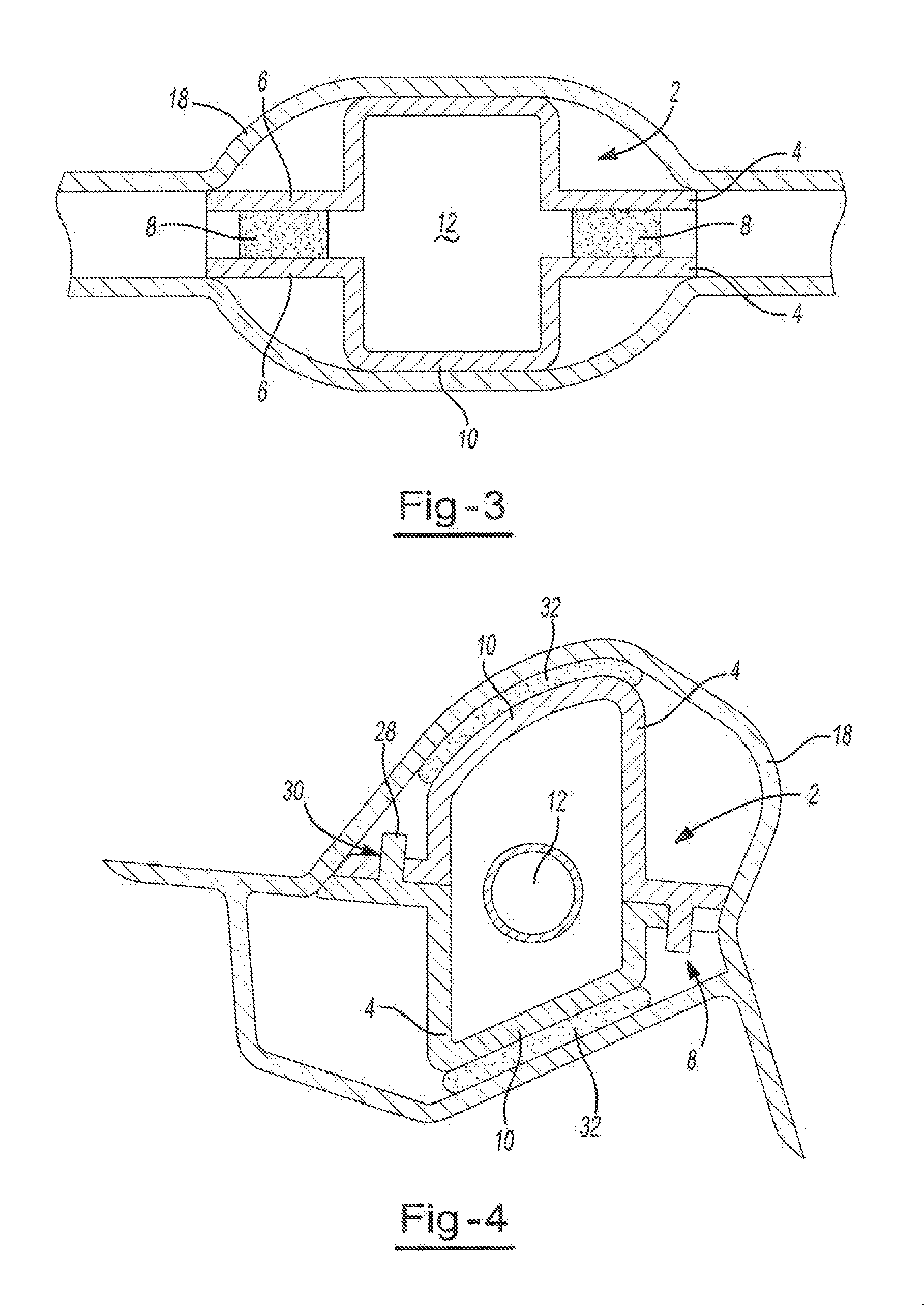
[0018]The present teachings are predicated upon providing an improved insert for providing reinforcement to a cavity. The insert includes a first carrier portion and a second carrier portion jointed together by an expandable reinforcement material. The first carrier portion and the second carrier portion when joined together form a channel therebetween.

[0019]Generally, the insert may be used in any device that includes a cavity where reinforcement is desired. The insert may be used with almost any vehicle (e.g. car, truck, bus, train, airplane, or the like). Alternatively, the inser...


PUM


Abstract

An insert comprising: a first carrier portion, the first carrier portion including: at least one attachment portion; a non attachment portion; and a portion of a channel, the channel being surrounded by the attachment portion and the non-attachment portion, and extending along all or a portion of the longitudinal axis of the first carrier portion; a second carrier portion, the second carrier portion including: at least one attachment portion; a non-attachment portion; and a portion of a channel, the channel being surrounding by the attachment portion and the non-attachment portion, and extending along all or a portion of the longitudinal axis of the second carrier portion; wherein the first carrier and the second carrier are attached via the respective at least one attachment portions forming a channel between the first carrier portion and the second carrier portion so that components, devices, fluids, or a combination thereof may pass through all or a portion of the insert.

Description

FIELD OF THE INVENTION[0001]The present invention generally relates to multiple carriers that for a channel between two or more carriers and form an insert.BACKGROUND OF THE INVENTION[0002]Typically inserts include a carrier covered by a reinforcement material. The carrier is one solid piece and the carrier is created without any internal hollow sections along the longitudinal axis of the insert. The inserts are placed in a cavity and adhere to the internal walls of the cavity; thus, reinforcing the cavity. The reinforcement material may expand so that the entire cavity is filled by the carrier and the reinforcing material. The inserts generally do not include any structure to allow for components, devices, fluids, or a combination thereof to pass though the longitudinal axis of the insert.[0003]One disadvantage faced by known inserts is that as the inserts become longer and longer (i.e., longer than 12 cm) it is no longer feasible to hollow out parts of the carrier to accommodate c...

Claims


Application Information

Patent Timeline
IPC IPC(8): F16L9/00
CPCF16L9/00B62D29/002B62D25/04
Inventor RICHARDSON, HENRYSKONIECZNY, DENNISLI, LIVEN
Owner ZEPHYROS INC
Why Eureka
Try Eureka