Co-Extruded Microchannel Heat Pipes

Active Publication Date: 2013-05-30
PALO ALTO RES CENT INC
View PDF30 Cites 0 Cited by
  • Summary
  • Abstract
  • Description
  • Claims
  • Application Information

AI Technical Summary

Benefits of technology

[0008]The present invention is directed to a microchannel heat pipe including a pipe body formed entirely by extruded primary material that is deposited on the surface of a substrate using an inexpensive co-extrusion process, and then cured or otherwise hardened to provide a pipe structure. Because the pipe body is formed

Problems solved by technology

In operation, heat generated in the high temperature region of the host device is absorbed at the high temperature end of the microchannel heat pipe, causing liquid working fluid to boil.
As the feature size of integrated circuits (ICs) decreases and transistor density increases, the heat flux of ICs increases and thermal management becomes more difficult.
Although the beneficial heat transfer performance of microchannel

Method used


Image

  • Co-Extruded Microchannel Heat Pipes
  • Co-Extruded Microchannel Heat Pipes
  • Co-Extruded Microchannel Heat Pipes

Examples


Example

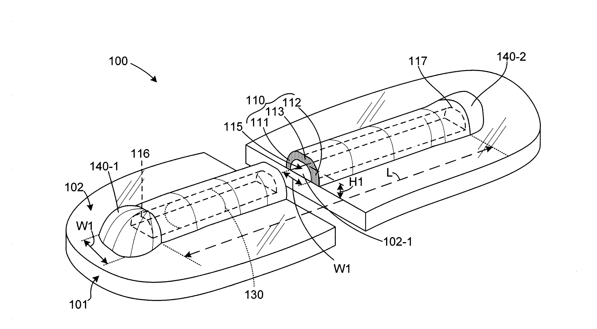
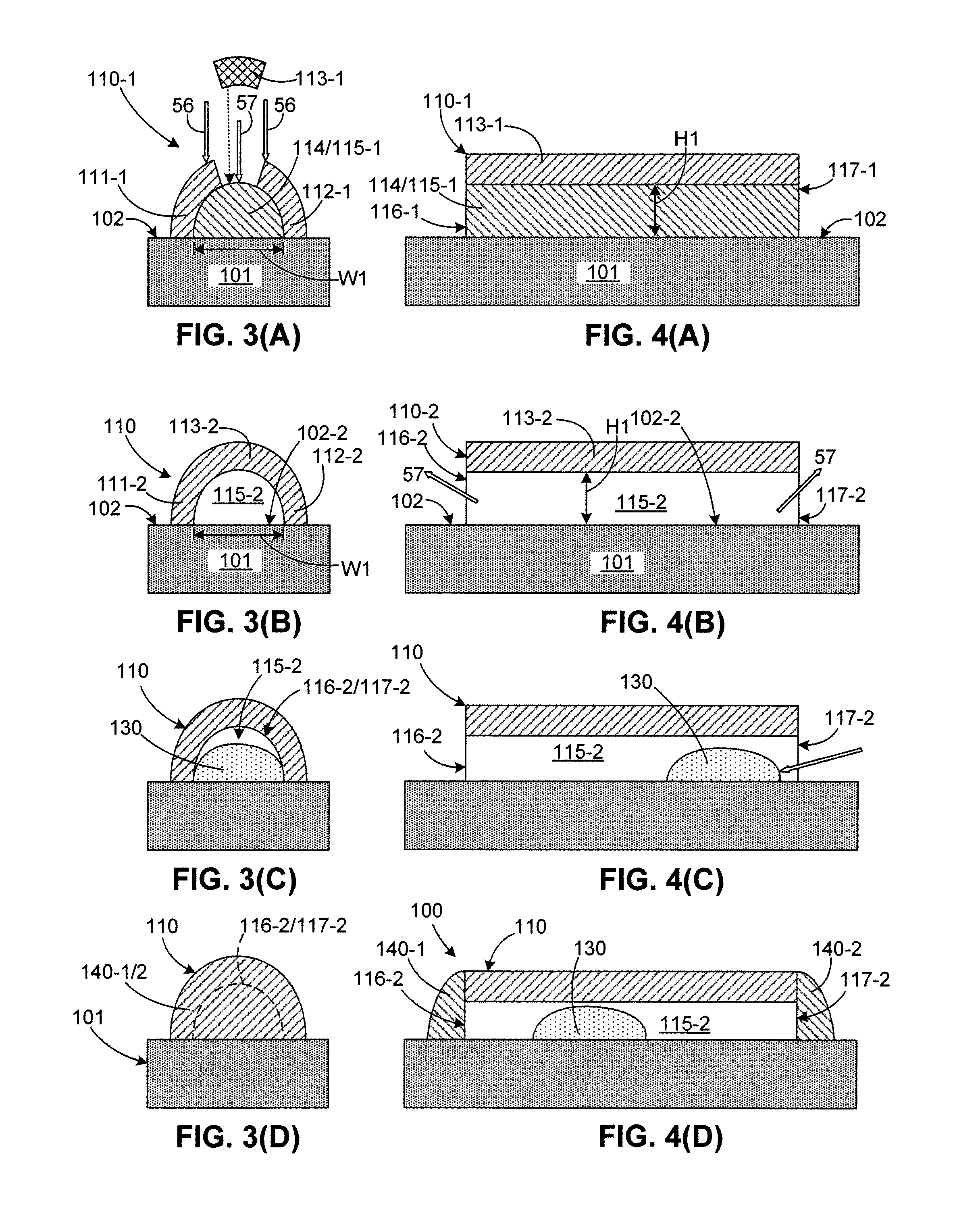
[0066]FIGS. 10(A) to 10(C) depict a first specific embodiment involving a two-part process that is utilized to produce elongated composite structures. FIG. 10(A) depicts a first part of the two-part process, and involves co-extruding a primary material 56A-1 and a secondary material 57A in the manner described above to produce a preliminary composite structure including side structures 111A-1 and 112A-1 and a central bead 114A disposed therebetween. Note that the preliminary composite structure shown in FIG. 10(A) is formed such that an upper surface of central bead 114A is exposed (i.e., not covered by primary material). FIG. 10(B) depicts composite structure 110A-1 after a second part of the two-part process in which a third material 56A-2 (which is either identical to primary material 56A-1 or suitably compatible) is extruded or printed onto the preliminary composite structure, whereby the third material forms an elongated upper portion 113A-1 that extends between upper edges of ...

Example

[0067]FIGS. 11(A) and 11(B) depict a second specific embodiment in which the co-extrusion process is performed using a modified co-extrusion printhead including a fourth nozzle inlet to the material merge point such that primary material 56B is simultaneously extruded onto the upper surface of secondary material 57B, which forms central bead 114B, whereby side portions 111B-1 and 112B-1 and an upper portion 113B-1 are formed during a single co-extrusion pass. Suitable printhead modifications capable of generating such vertical layering are described, for example, in co-owned U.S. Pat. No. 7,765,949, which is incorporated herein by reference in its entirety. FIG. 11(A) depicts composite structure 110B-1 formed by this method immediately after the co-extrusion process, and FIG. 11(B) depicts a resulting pipe structure 110B-2 after subsequent curing / hardening of the primary material to form side walls 111B-2 and 112B-2 and an upper wall 113B-2, and the removal of the secondary material...

Example

[0068]FIGS. 12(A) to 12(C) depict a third specific embodiment involving polymerization of a portion of the co-extruded primary and secondary materials to form a polymer structure that serves as the desired rigid pipe body. FIG. 12(A) depicts the co-extrusion of a primary material 56C and a secondary material 57C using any of the techniques described above to produce a preliminary composite structure 110C-1 including side portions 111C-1 and 112C-1, a central bead 114C disposed therebetween, and an upper portion 113C-1 that extends over central bead 114C. In this embodiment primary material 56C includes both a catalyst and a monomer, and FIG. 12(B) depicts a subsequent polymerization process that causes at least a portions of the primary material forming side portions 111C-1 and 112C-1 and upper portion 113C-1 to generate a polymer structure (pipe body) 110C-2 that surrounds central bead 114C. In one specific embodiment the catalyst comprises an ultraviolet (UV) reactive material, an...


PUM

PropertyMeasurementUnit
Lengthaaaaaaaaaa
Lengthaaaaaaaaaa
Lengthaaaaaaaaaa

Abstract

A microchannel heat pipe formed on a substrate surface using co-extruding a primary material and a secondary material such that the primary material forms side wall portions that are spaced apart by the secondary material, and an upper wall portion is formed across the upper ends of the side walls to form a composite structure. After the primary material hardens, the secondary material is removed, whereby the hardened primary material forms a pipe body having an elongated central channel defined between opposing end openings. A working fluid is then inserted into the elongated central channel, and sealing structures are then formed over both end openings to encapsulate the working fluid.

Description

FIELD OF THE INVENTION[0001]This invention relates to microchannel heat pipes and devices that include microchannel heat pipes, and more particularly methods for producing microchannel heat pipes on such devices.BACKGROUND OF THE INVENTION[0002]Heat pipes are heat transfer devices with high effective thermal conductivities that are used to transfer heat from a high temperature region to a low temperature region by way of a heat transfer fluid (referred to herein as a “working fluid”), whereby a temperature at the high region may be stabilized or reduced.[0003]Microchannel heat pipes are heat pipes having a closed channel with a small (often on the order of tens of micrometers) and angled (often triangular) cross section, and are partially filled with a working fluid (often methanol, ethanol, water, acetone, or ammonia). One end of the heat pipe (the “evaporator” section) is placed in contact with a relatively high temperature region of a host device (e.g., an integrated circuit or a...

Claims


Application Information

Patent Timeline
IPC IPC(8): F28D15/04
CPCF28F21/062F28F21/08F28D15/0233F28F2260/02B23P2700/09F28D15/04H01L23/427B23P15/26F28F2255/16F28D15/046H01L2924/0002H01L2924/00
Inventor SCHWARTZ, DAVID ERICRAO, RANJEET BALAKRISHNA
Owner PALO ALTO RES CENT INC
Why Eureka
Try Eureka