Method for Localizing Sources of Signals in Reverberant Environments Using Sparse Optimization

Inactive Publication Date: 2014-08-28
MITSUBISHI ELECTRIC RES LAB INC
View PDF3 Cites 2 Cited by
  • Summary
  • Abstract
  • Description
  • Claims
  • Application Information

AI Technical Summary

Benefits of technology

[0008]The embodiments of the invention provide a method for localizing sources of signals in reverberant environments. By formulating the localization problem in a frequency domain, the method can efficiently incorporate information that exploits the reverberation instead of considering it a nuisance to be suppressed.
[0009]In this formulation, localization becomes a joint-sparsity

Problems solved by technology

where an l0 norm counts the number of non-zero coefficients of

Method used


Image

  • Method for Localizing Sources of Signals in Reverberant Environments Using Sparse Optimization
  • Method for Localizing Sources of Signals in Reverberant Environments Using Sparse Optimization
  • Method for Localizing Sources of Signals in Reverberant Environments Using Sparse Optimization

Examples


Embodiment Construction

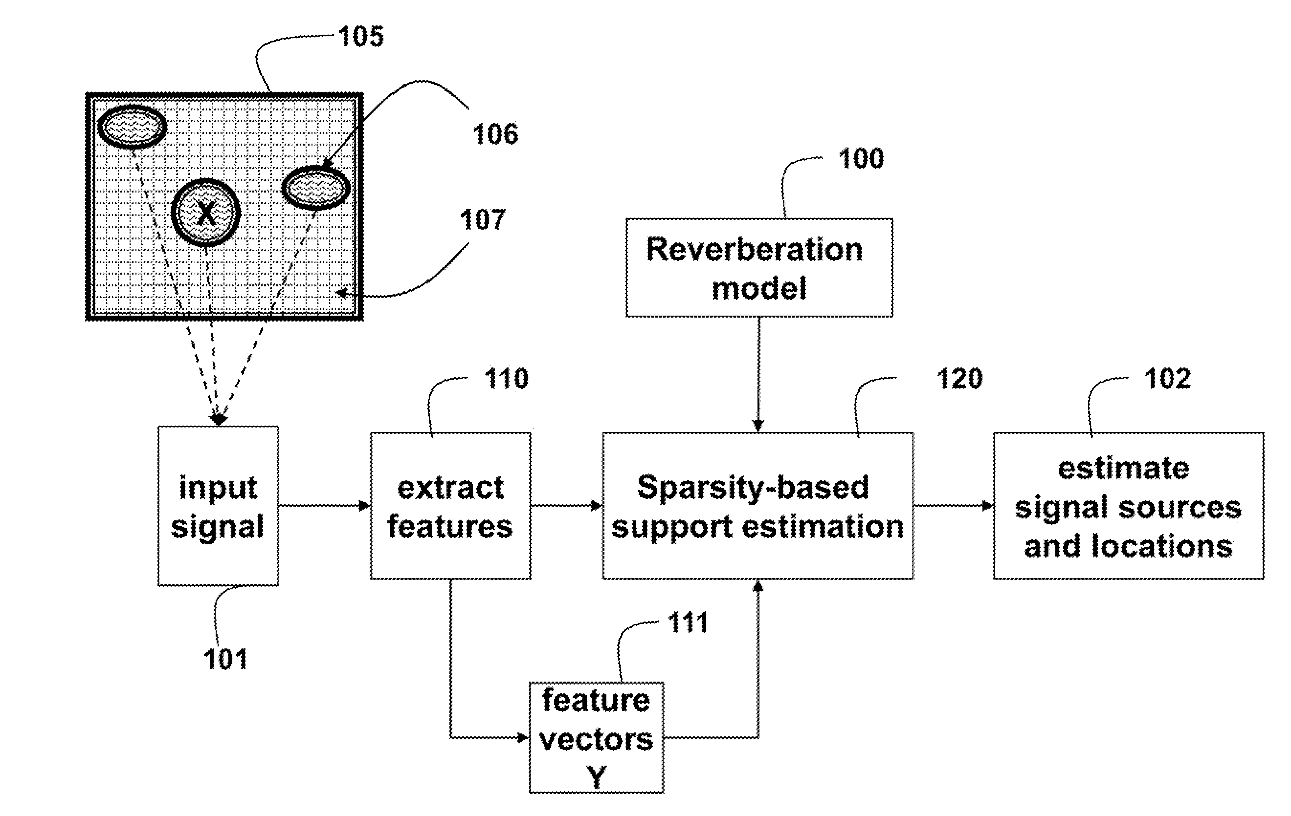
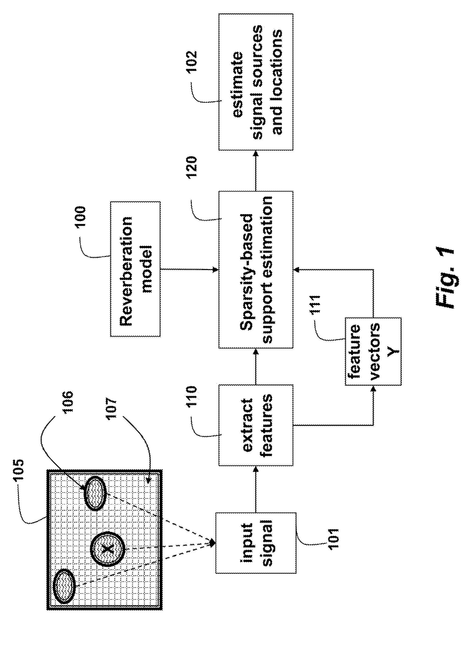
[0013]As shown in FIG. 1, embodiments of our invention provide a method for localizing source signals 106 emitted in a reverberant environment 105 using sparse optimization.

[0014]Input signals 101 are acquired from the sources by a set of sensors. For example, the signals are acoustic signals and the sensors are microphones. The input signal at each frequency is modeled as a linear combination of all the source signals at that particular frequency. Coefficients in the linear combination correspond to a frequency response of the environment from each location at that frequency.

[0015]However, it is understood that other signaling modalities can be used by the embodiments of the invention.

[0016]Features extracted 110 from the input signals produce a feature vector 111. The specific features used depend on the signaling modality. In the following we assume that the input signal is usually in the form of a feature vector, although we do not say so explicitly each time.

[0017]A sparsity-ba...


PUM


Abstract

Source signals emitted in a reverberant environment from different locations are processed by first receiving input signals corresponding to the source signals by a set of sensors. Then, a sparsity-based support estimation is applied to the input signals according to a reverberation model to produce estimates of the source signals and locations of a set of sources emitting the source signals.

Description

FIELD OF THE INVENTION[0001]This invention relates generally to signal processing, and more particularly to localizing sources of signals in reverberant environments.BACKGROUND OF THE INVENTION[0002]Compressive Sensing and Sparse Models[0003]Compressive sensing (CS) and sparse models provide theories and tools for signal acquisition and signal processing applications. A sparse model assumes that a signal, when transformed to an appropriate basis, has very few significant coefficients that model signal energy. Promoting sparsity in some appropriate domain is a very efficient computational method to capture the structure of most natural and man-made signals processed by modern signal processing systems.[0004]Sparsity is useful when inverting an undetermined linear system of the formy=Ax,  (1)where y is an M-dimensional measurement vector, A is a mixing matrix, and x is an N dimensional sparse signal vector. For the underdetermined system, the following optimization determines a sparse...

Claims


Application Information

Patent Timeline
IPC IPC(8): G06F17/10
CPCG06F17/10G01S3/802G10L21/0208G06F18/21345G06F18/2136
Inventor BOUFOUNOS, PETROS T.LE ROUX, JONATHANKANG, KANGHERSHEY, JOHN R.
Owner MITSUBISHI ELECTRIC RES LAB INC
Why Eureka
Try Eureka