X-ray analysis apparatus

Active Publication Date: 2013-05-30
RIGAKU CORP
View PDF4 Cites 18 Cited by
  • Summary
  • Abstract
  • Description
  • Claims
  • Application Information

AI Technical Summary

Benefits of technology

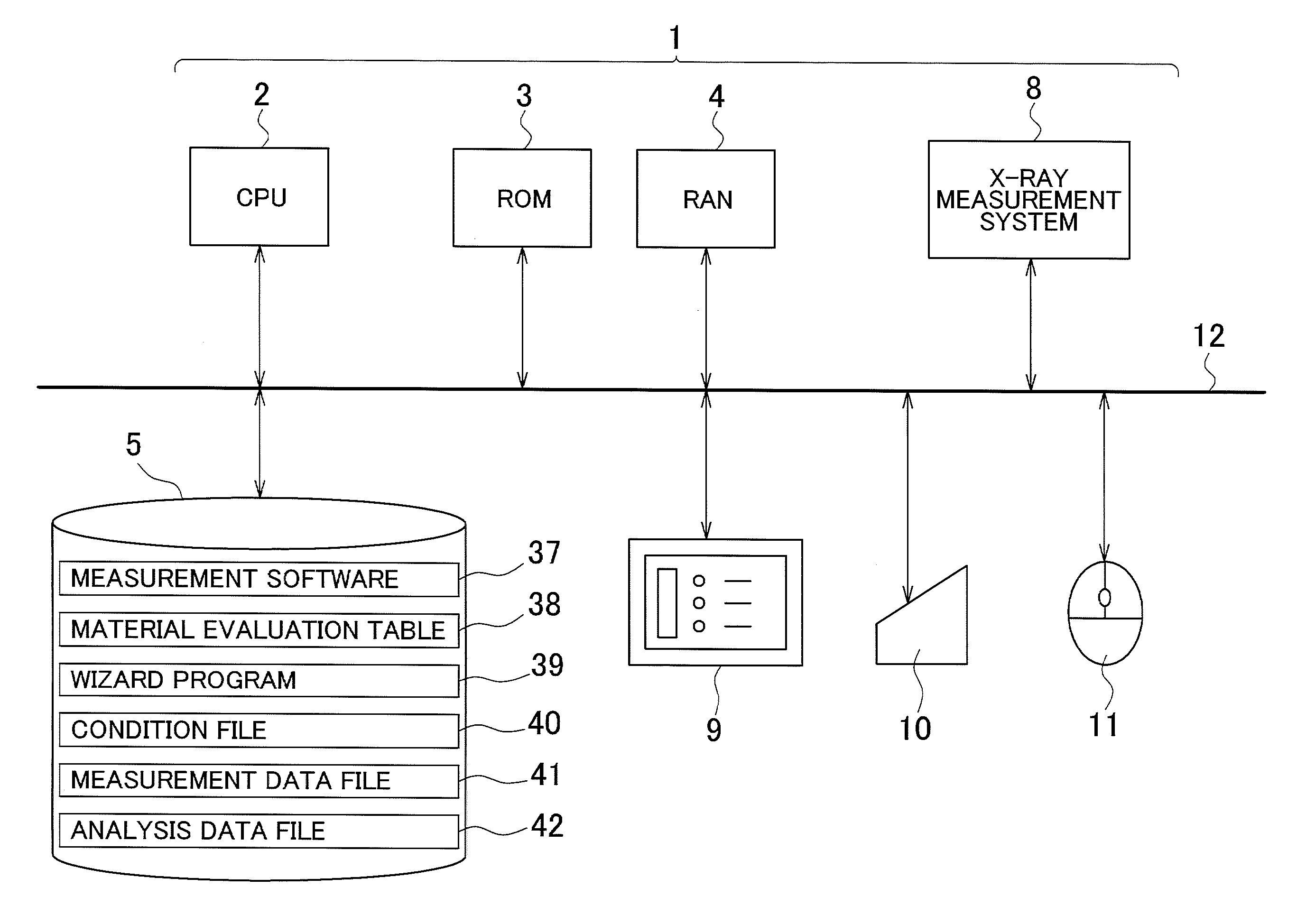
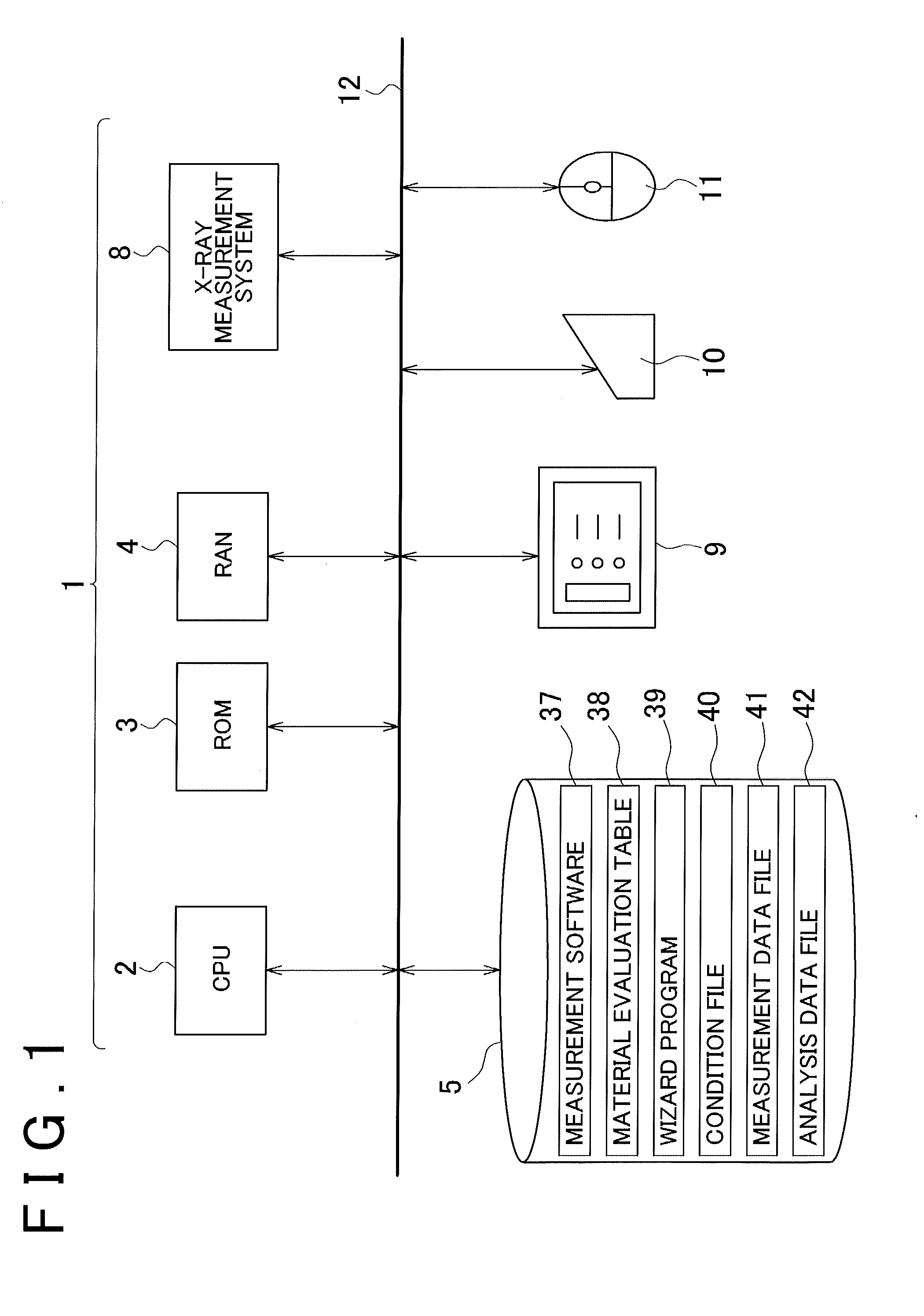
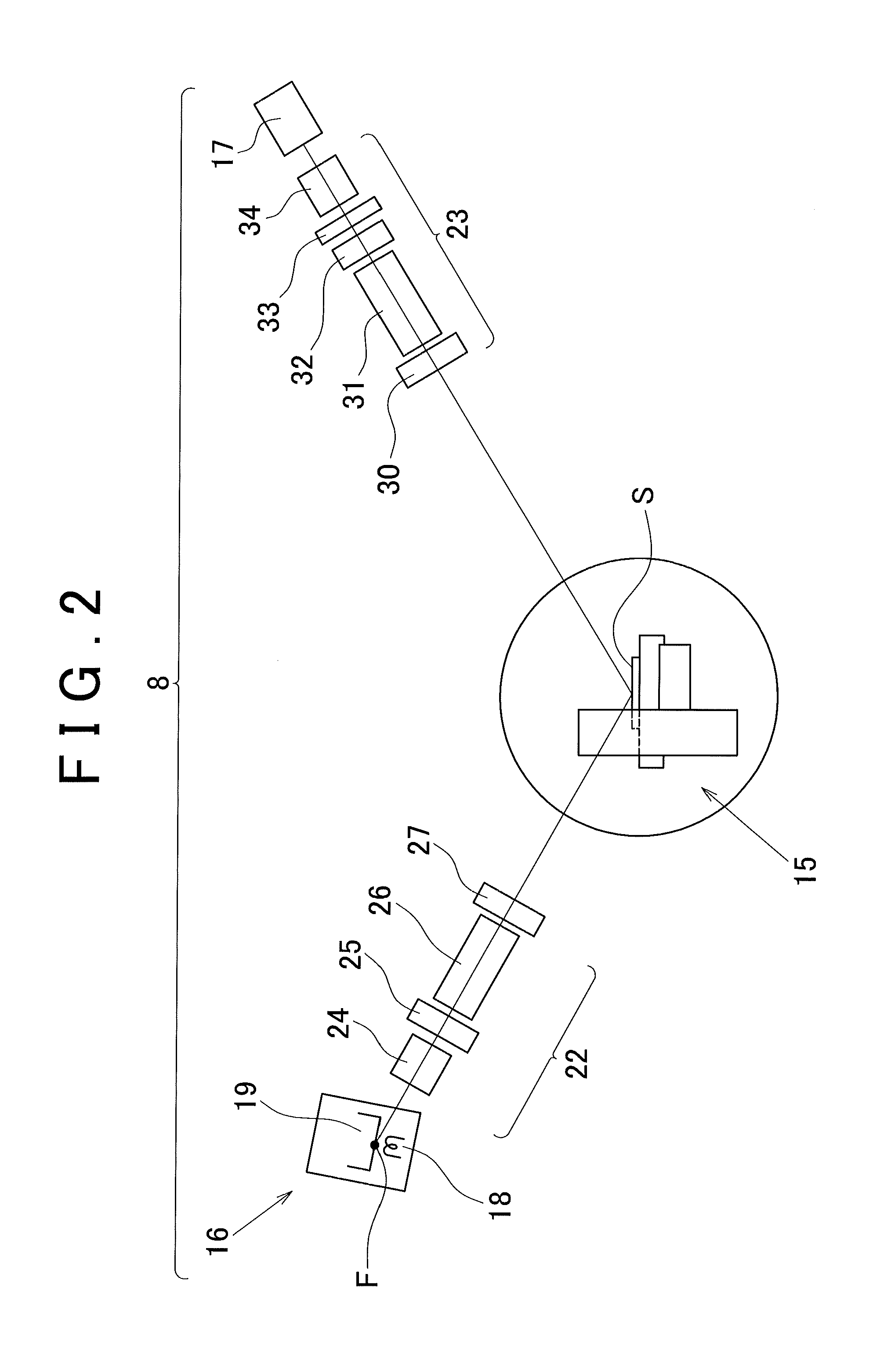
[0038]The X-ray analysis apparatus according to the third aspect is an X-ray analysis apparatus having a function enabling a plurality of measurement methods (in-plane measurement, rocking curve measurement, and the like) to be implemented. According to this X-ray analysis apparatus, when a plurality of measurement methods are successively executed, in an instance in which a function of a part step included in the first macro, which is one of the macros corresponding to each of the measurement methods, encompasses a function of a part step included in a second

Problems solved by technology

However, deciding, with respect to a given combination of material and material field, the category for evaluation to be set, the measurement method to be employed, and the optical system to be employed is extremely difficult even for an experienced engineer, and is almost impossible for an operator lacking in knowledge of X-ray measurement.
Howeve

Method used


Image

  • X-ray analysis apparatus
  • X-ray analysis apparatus
  • X-ray analysis apparatus

Examples


Example

First Embodiment of Measurement Macro

[0185]In basic terms, the CPU 2 creates a macro when the material information shown in FIG. 5 (i.e., “material field” in the first column and “material” in the second column) has been decided, the evaluation (third column) has been decided, and the measurement method (fourth column) and the optical system (fifth column) have been decided.

[0186]For example, in an instance in which, in FIG. 5, “phase identification” is selected in “selection of evaluation” in the third column, and “in-plane measurement” is selected in “selection of measurement method” in the fourth column, a macro shown, e.g., in FIG. 17A is created.

[0187]In an instance in which “study lattice constant” is selected in “selection of evaluation” in the third column, and “direction within surface plane” is selected in “selection of measurement method” in the fourth column, a macro shown, e.g., in FIG. 17B is created.

[0188]In an instance in which “study degree of alignment” is selected...

Example

Second Embodiment of Measurement Macro

[0195]FIGS. 19A through 19C show another embodiment relating to the creation of a macro. This embodiment is one in which two types of evaluation shown in FIGS. 19A and 19B are selected at the same time. In this instance, the two types of macro have stages 1 and 2 (part steps 1 and 2) in common with each other, and the common stages can be shared.

[0196]Looking at stage 3 (part step 3) of these macros, the corresponding stages differ; therefore, it can be thought, in basic terms, that the stages cannot be shared. However, stage 3 of macro (a) is “in-plane sample position adjustment” and stage 3 of macro (b) is “sample position adjustment.” In this instance, with regard to adjustment accuracy, it is necessary to set the accuracy of the in-plane sample position adjustment so as to be higher than the accuracy of the sample position adjustment. This means that once the in-plane sample position adjustment has been performed, the positional accuracy is ...


PUM


Abstract

An X-ray analysis apparatus having a function for enabling a plurality of measurement methods to be implemented, the X-ray analysis apparatus having: a measurement system capable of implementing a plurality of measurement methods; measurement software for implementing, in a selective manner, each of the measurement methods; a material evaluation table for storing information relating to a material that may be measured, and a name of an evaluation performed on the material; an input device for inputting the information relating to the material; a wizard program for performing computation for selecting the name of an evaluation on the basis of the information relating to the material inputted using the input device; and a wizard program for selecting a corresponding measurement method on the basis of the selected name of the evaluation.

Description

BACKGROUND OF THE INVENTION[0001]1. Field of the Invention[0002]The present invention relates to an X-ray analysis apparatus having a function enabling a variety of measuring methods to be implemented.[0003]2. Description of the Related Art[0004]In recent years, there have been proposed X-ray analysis apparatuses having a function enabling a variety of measuring methods to be implemented. For example, according to Patent Citation 1, it is disclosed that X-ray diffraction measurement, X-ray small-angle scattering measurement, reflectivity measurement, and other measurement methods in which X-ray is used are performed using a single X-ray analysis apparatus.[0005]According to, e.g., Patent Citation 2, there is disclosed an X-ray analysis apparatus in which the measurement method is predefined, the X-ray analysis apparatus making it possible to readily select, using a computer, a measurement condition that corresponds to the characteristics of the substance to be measured.[0006](Patent...

Claims


Application Information

Patent Timeline
IPC IPC(8): G06F17/00
CPCG06F17/00G01N2223/306G01N23/20G01N23/207
Inventor MITSUNAGA, TORUMORIKAWA, KEIICHIINABA, KATSUHIKO
Owner RIGAKU CORP
Why Eureka
Try Eureka