Attachment arrangement, a connecting device, and also a method

a technology of connecting device and attachment, which is applied in the direction of coupling, rod connection, manufacturing tools, etc., can solve the problems of severe load on the attachment, however, and the installation of the attachment arrangement as described, so as to reduce the installation time, reduce the final installation, and simplify the installation

Active Publication Date: 2013-06-06
AIRBUS OPERATIONS GMBH
View PDF2 Cites 10 Cited by
  • Summary
  • Abstract
  • Description
  • Claims
  • Application Information

AI Technical Summary

Benefits of technology

[0017]A preferred connecting device for an inventive attachment arrangement has a connecting element and a receiving element, of which the one element can be arranged on a component section and the other element can be arranged on a base item section, and which in the installed state detachably engage with one another in a form fit, wherein loads can be transferred at least in the direction of a primary axis, and relative movements are possible between the elements in the direction of a movement axis. Such a connecting device enables force-fitted or materially-bonded connections, such as a riveted joint, a pinned joint or an adhesively bonded joint, to be dispensed with, and by this means significantly simplifies the installation.
[0018]In a preferred method for attaching a component to a base item using an inventive attachment arrangement, a primary axis and a movement axis are firstly defined. The at least one connecting device is then pre-installed on the component and the base item, aligned with the primary axis and the movement axis. The component is then installed on the base item and is then fixed in location by means of at least one fixing device on a section on the base item. Such a method enables the installation time to be reduced since the connecting device is pre-installed and thus reduces the final installation by a corresponding number of installation steps. Moreover in the region of a section of the component or base item that is difficult to access, an attachment can be undertaken by means of the connecting device. In addition the number of interdependent tolerances on the fixing devices is reduced.

Problems solved by technology

The attachment arrangements as described are however technically complex to install, in particular if the attachment must be made to structural sections that are difficult to access.
Moreover the attachment arrangements do not enable any compensation for distortions, as a consequence of varying in-flight loads, for example, so that constraint forces are regularly introduced into the components, and moreover the attachments are severely loaded.

Method used


Image

  • Attachment arrangement, a connecting device, and also a method
  • Attachment arrangement, a connecting device, and also a method
  • Attachment arrangement, a connecting device, and also a method

Examples


Embodiment Construction

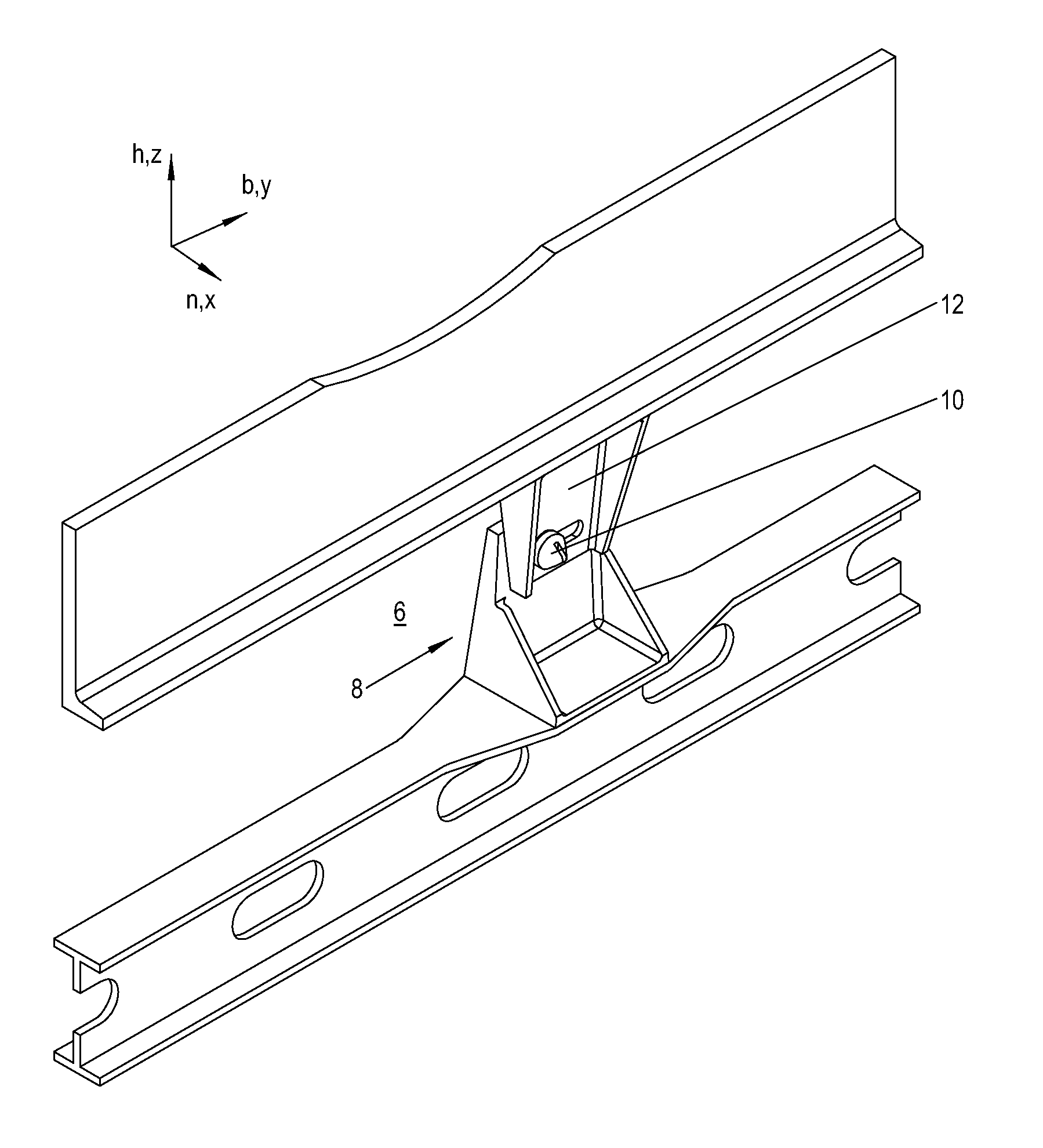
[0038]FIG. 1 shows in a scrap section the attachment of a component 2 to a base item 4 by means of an inventive attachment arrangement 6. The component 2 is, for example, a secondary support structure of an aircraft for purposes of accommodating installation lines, cabin systems and similar. The base item 4 is, for example, a primary structure of the aircraft, such as a transverse floor beam.

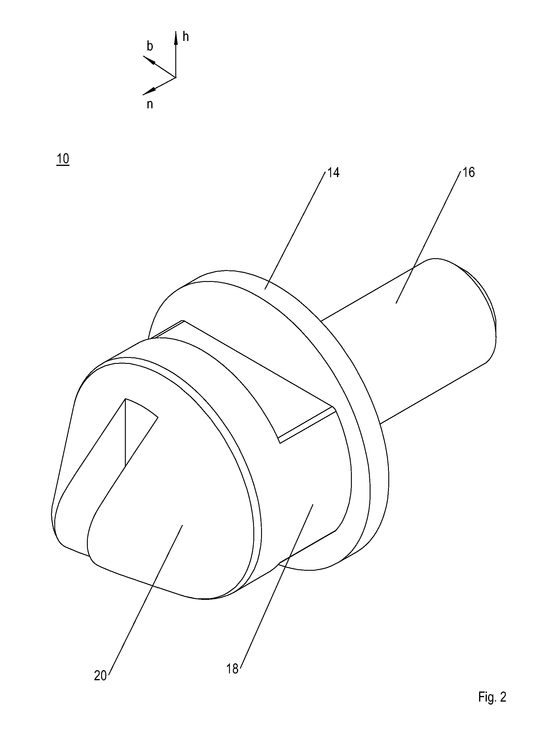
[0039]The attachment arrangement 6 has at least one fixing device, not shown, and at least one connecting device 8. The fixing device serves to fix the location of a region of the component 2 on a region of the base item 4 in all axis directions. In the example of embodiment shown in FIG. 1 the connecting device 8 serves the purpose of transferring primary loads in the direction of a primary axis h without any play. Secondary loads can be transferred between the component 2 and the base item 4 in the direction of a secondary axis n that runs transverse to the primary axis h, wherein, depending u...


PUM

PropertyMeasurementUnit
opening forceaaaaaaaaaa
flexibilityaaaaaaaaaa
constraint forcesaaaaaaaaaa

Abstract

An attachment arrangement for attaching a component to a base item, with at least one fixing device for fixing one section of the component on a section of the base item. At least one connecting device with a connecting element and at least one receiving element are provided. One of the elements is arranged on a component section and the other of the elements is arranged on a base item section. The two elements detachably engage with one another in a form fit. Loads can be transferred at least in the direction of a first axis, and a relative movement is possible between the elements in the direction of a second axis, different from the first axis. A connecting device is disclosed for such an attachment arrangement. A method is disclosed for purposes of attaching a component to a base item by means of such an attachment arrangement.

Description

BACKGROUND OF THE INVENTION[0001]The invention concerns an attachment arrangement for purposes of attaching a component to a base item, a connecting device for such an attachment arrangement, and also a method for purposes of attaching a component to a base item.[0002]Components in aircraft, such as cabin components, power, signal, or data cables, structural elements, and similar, are regularly fixed in location in the x, y, and z directions to a base item, e.g., to an aircraft structure. The type of fixing is thereby matched to the type of component. Thus, for example, cables, or cable harnesses, are often directly attached to their respective structural sections by means of cable binders. As shown in DE 10 2006 053 966 A1 and also in DE 10 2009 022 175 A1, the cable harnesses can however also be attached to the structural sections in combination with so-called “snap and click” connectors. Components such as transverse beams are regularly riveted to frames, as shown in DE 10 2009 0...

Claims


Application Information

Patent Timeline
Patent Type & Authority Applications(United States)
IPC IPC(8): F16B7/00
CPCF16B7/00H02G3/30Y10T29/49947F16B21/09Y10T403/32008F16B5/0628
Inventor EILKEN, WOLFGANGTIRYAKI, MEMISSAUER, DANIEL
Owner AIRBUS OPERATIONS GMBH
Why Eureka
Try Eureka