Tumble dryer having a fire extinguishing system

a fire extinguishing system and tumble dryer technology, applied in the direction of drying machine combinations, drying machines with progressive movements, lighting and heating apparatus, etc., can solve the problems of failure of test, fire may occur, and fire cannot be completely ruled out, so as to achieve simple but nevertheless safe construction

Inactive Publication Date: 2013-06-06
BSH BOSCH & SIEMENS HAUSGERAETE GMBH
View PDF4 Cites 7 Cited by
  • Summary
  • Abstract
  • Description
  • Claims
  • Application Information

AI Technical Summary

Benefits of technology

[0013]An object of the invention is therefore to provide a tumble dryer having a fire extinguishing device in the drum, which represents a simple but nevertheless safe construction for extinguishing a fire and still continues to function even if the fire has already interrupted the power supply of the domestic appliance.
[0016]The tumble dryer according to the invention is characterized in that at least one of the containers has a cavity filled with an extinguishing medium and at least one release device for the extinguishing medium, the release device being designed so that it is activated in the event of a fire starting or having started in the drum, with the result that an opening to the cavity of the container is produced. The container is arranged either on the radial internal wall of the drum or on at least one of the two end walls of the drum. The container is for example a drum paddle or even a component which has no paddle function. This component is for example a thin circular annular shaped or circular annular segment shaped cavity body which is fitted on the radial internal wall of the drum or one of the two end walls. In one embodiment, in addition to the drum paddles filled with extinguishing medium at least one component can be arranged in the interior of the drum. In a preferred embodiment, the component(s) is / are not arranged over the entire length of the drum so as to avoid an unnecessary loss of space in the interior of the drum. By preference, they are however distributed evenly over the circumference of the drum in order to avoid imbalance.
[0018]The advantages which can be achieved with the invention are seen to consist in the fact that the tumble dryer is protected with a high level of confidence against the danger of a fire because in the event of a fire in the drum a fire extinguishing device is activated, the extinguishing medium for which is located directly in the drum and does not need to be first pumped into the drum. Since the present invention is concerned with a purely mechanical solution, it is independent of the power supply for the domestic appliance, and furthermore particularly cost-effective. The tumble dryer is therefore designed so as to release extinguishing medium without propellant in the drum.
[0019]As a result of introducing an extinguishing medium the fire is extinguished more quickly than in comparison with an uninfluenced fire in the drum interior. By this means, the risk of the fire spreading or of the fire escaping from the drum is reduced.
[0022]At least one of the containers designed as a hollow body has at least one release device. By preference however, it has a plurality of release devices. The release device(s) serves / serve as a “predetermined breaking point” in the cavity wall and melt first under the influence of heat, in other words they melt before the surrounding cavity wall of the container. The release device is therefore melted open in the case of a fire starting or having started in the drum, with the result that an opening to the cavity of the container is produced and the extinguishing medium enters the drum and is thus able to extinguish the fire which is starting or has started. Since the fire in the drum can easily reach temperatures of 500° C. to 800° C. and higher, it is sufficient if the predetermined breaking points already melt below this temperature range, for example at temperatures above 150° C., preferably at 200° C. to 450° C. The release device is therefore a purely mechanical device and independent of the power supply of the tumble dryer.

Problems solved by technology

The problem is furthermore known that a fire may occur in the event of overheating in rare exceptional cases.
In particular when drying textiles having a very high and fine lint content, or in the case of a blockage in an air channel, a fire cannot be completely ruled out.
Should the cloth ignite, the test is considered to have been failed and the machines may not be sold on the US market.

Method used


Image

  • Tumble dryer having a fire extinguishing system
  • Tumble dryer having a fire extinguishing system
  • Tumble dryer having a fire extinguishing system

Examples


Embodiment Construction

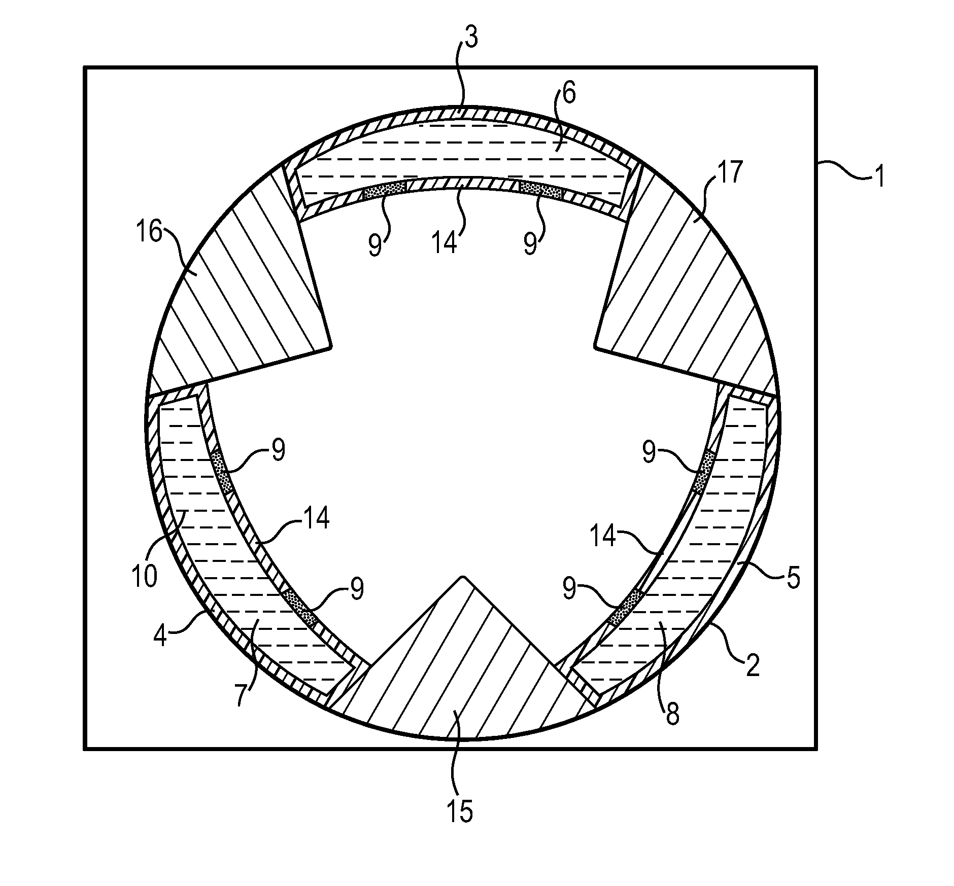
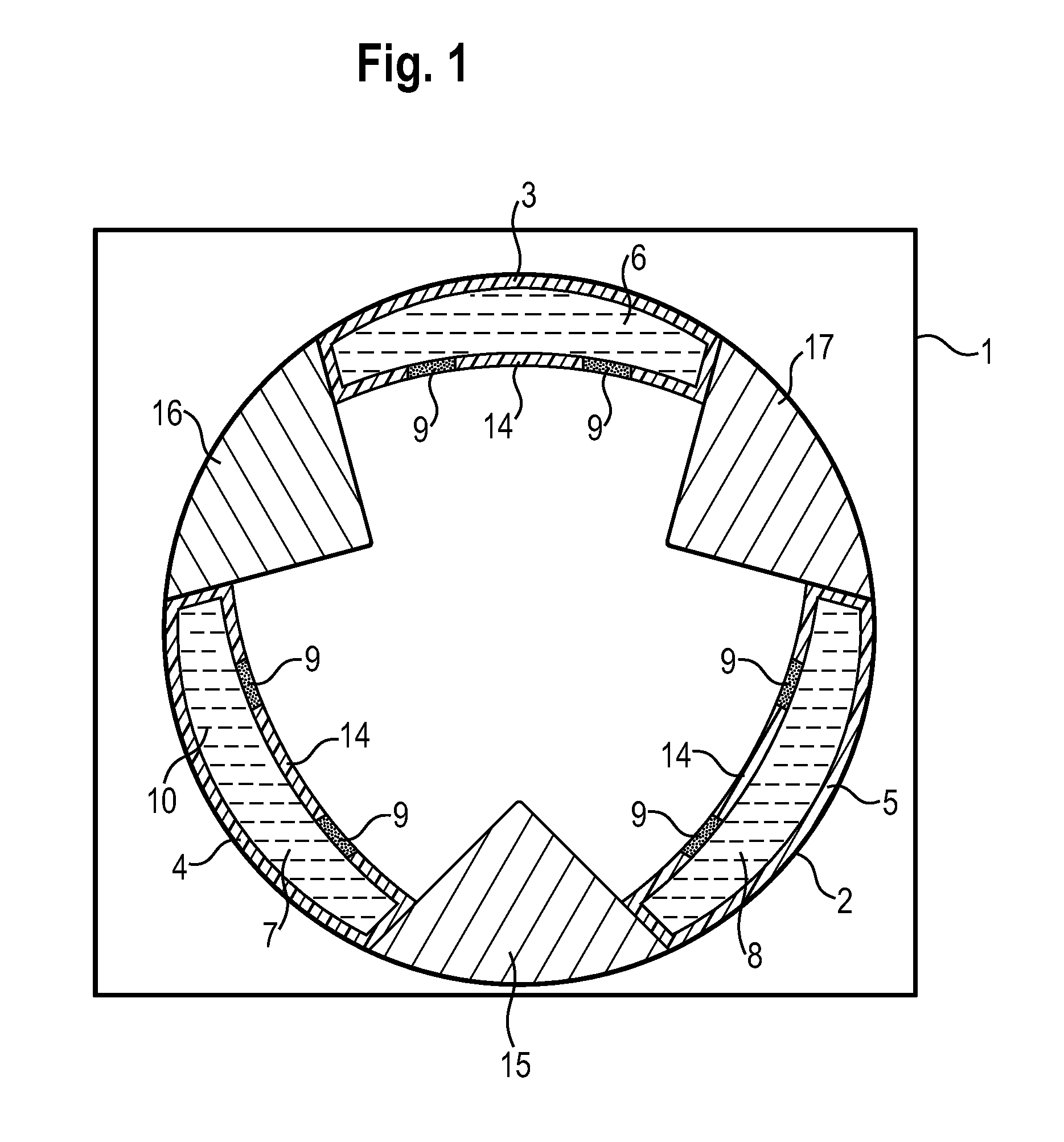
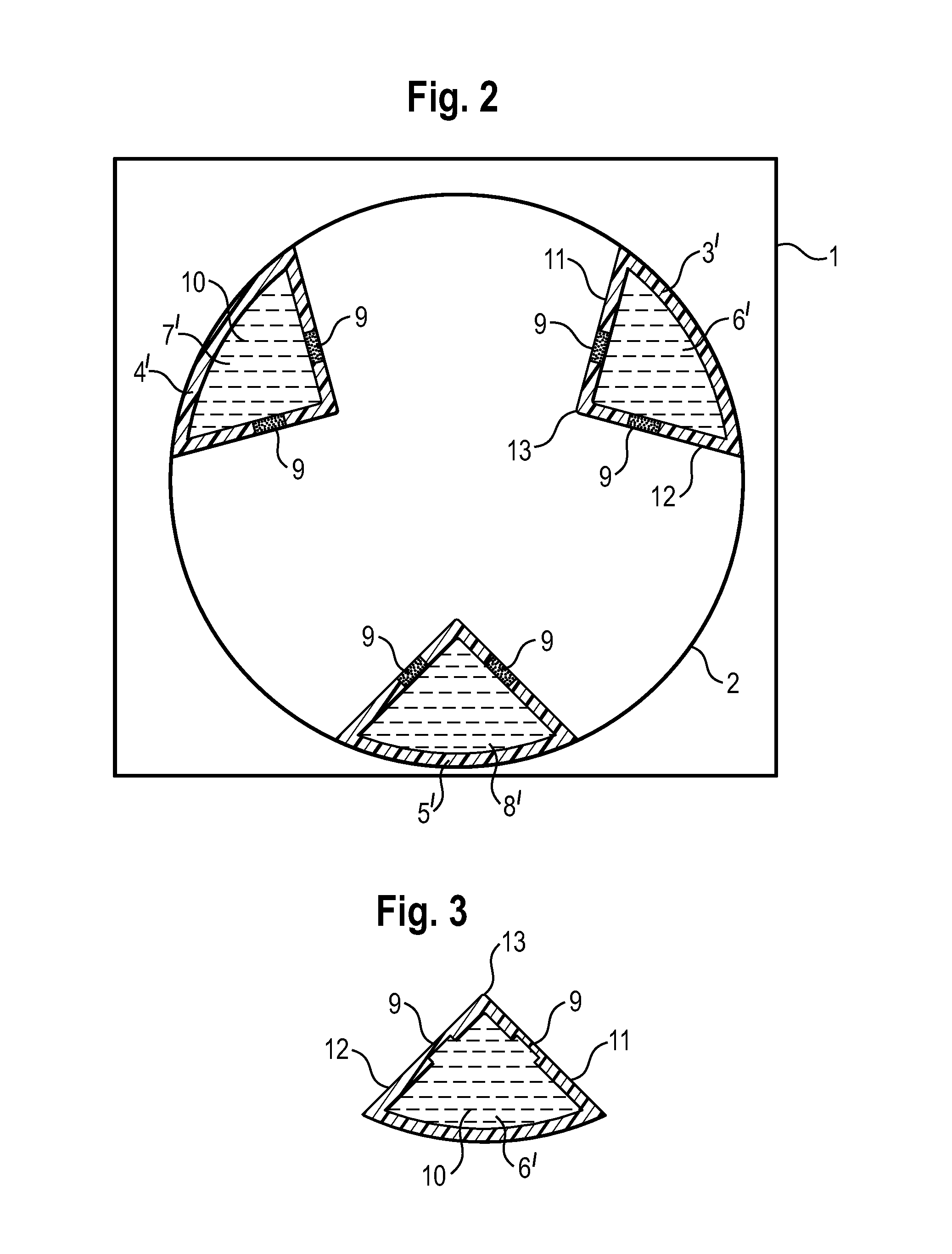
[0039]FIG. 1 schematically shows a cross-section through a drum of a tumble dryer 1, wherein the drum 2 can rotate around a horizontal axis and the containers 3, 4, 5 are mounted on the internal walls of the drum. In this embodiment the containers are components having no paddle function and are mounted directly on the internal wall of the drum. In addition, on its internal wall the drum has the paddles 15, 16 and 17 for agitating the laundry while the drum is moving. In this embodiment the paddles 15, 16, 17 have a V-shaped profile. The containers each have a thin circular annular segment shaped profile. Each of the containers has at least one cavity 6, 7, 8 and also a plurality of release devices 9 in the walls 14 which face the interior of the drum. In this embodiment the release devices 9 are represented as elongated slots. The entire cavity of the containers is filled with water or extinguishing powder 10. The containers 3, 4, 5 and the release devices 9 are produced from diffe...


PUM


Abstract

A tumble dryer includes a drum which has an interior for holding laundry items, and at least one container which is received in the interior of the drum. The container has a cavity which is filled with an extinguishing medium. At least one release device is arranged in a cavity wall of the container for the extinguishing medium and is activated in the event of a fire starting or having started in the drum to thereby provide an opening to the cavity of the container.

Description

BACKGROUND OF THE INVENTION[0001]The invention relates to a tumble dryer, in particular a domestic tumble dryer having a fire extinguishing device.[0002]Generally known tumble dryers have as a general rule a cylindrical drum for holding the laundry, which drum is arranged in rotatable fashion around a horizontal axis. In this situation a warm air current is normally fed in or out by way of the end walls of the drum. It is also known to provide paddles in the drum of tumble dryers in order to set the laundry in motion when the drum is rotating and to achieve a better warm air flow through the laundry.[0003]The problem is furthermore known that a fire may occur in the event of overheating in rare exceptional cases. In particular when drying textiles having a very high and fine lint content, or in the case of a blockage in an air channel, a fire cannot be completely ruled out. Accordingly, high demands are placed on tumble dryers in order to design them such that any possible fire is n...

Claims


Application Information

Patent Timeline
Patent Type & Authority Applications(United States)
IPC IPC(8): F26B20/00
CPCF26B20/00F26B25/009D06F2058/2858D06F58/04D06F58/28D06F58/20D06F37/42D06F58/50D06F2103/00D06F2105/00
Inventor STEGERWALD, GERHARD
Owner BSH BOSCH & SIEMENS HAUSGERAETE GMBH
Why Eureka
Try Eureka