
Zoom lens and imaging device using same

a technology which is applied in the field of zoom lens and imaging device, can solve the problems of increasing the overall size adding to the overall complexity of the imaging device,

Inactive Publication Date: 2013-06-06
FOSHAN PREMIER SCI & TECH CO LTD +1
View PDF2 Cites 7 Cited by
  • Summary
  • Abstract
  • Description
  • Claims
  • Application Information

AI Technical Summary

Benefits of technology

The patent is about an imaging device that includes several components, such as a fixed barrel, gear barrel, outer guiding barrel, front guiding barrel, cam barrel, inner guiding barrel, lens unit, and other parts. The device is designed to capture images with high quality and precision. The technical effects of this patent include improved image quality, reduced image blurring, and improved focus and control over the image capture process.

Problems solved by technology

However, the detecting unit, the calculating unit and the blur correcting unit each have a complicated structure and add to the overall complexity of the imaging device, and increase the overall size of the imaging device.

Method used


Image

  • Zoom lens and imaging device using same
  • Zoom lens and imaging device using same
  • Zoom lens and imaging device using same

Examples


Embodiment Construction

[0021]Embodiments of the disclosure will be described with reference to the accompanying drawings.

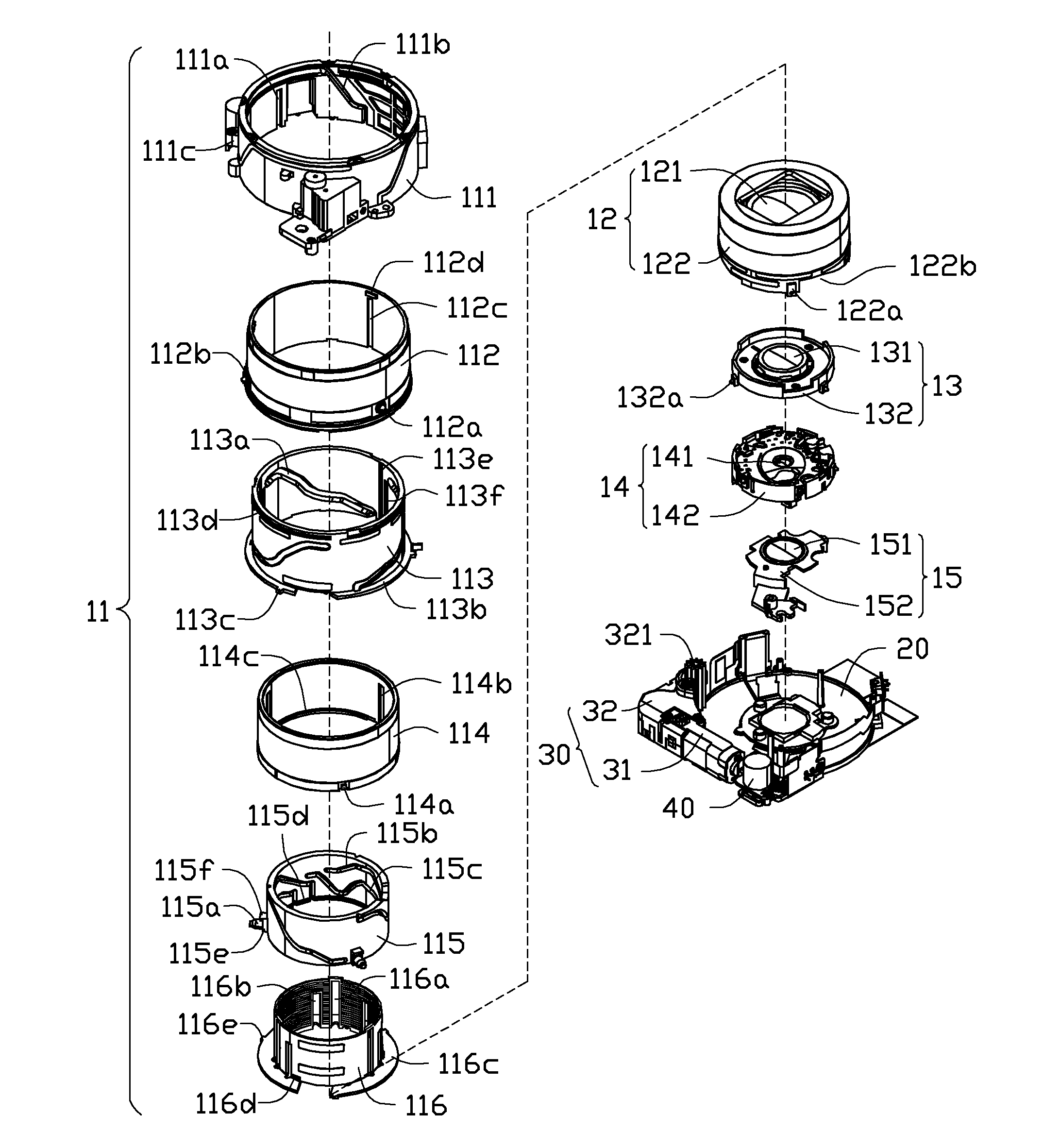
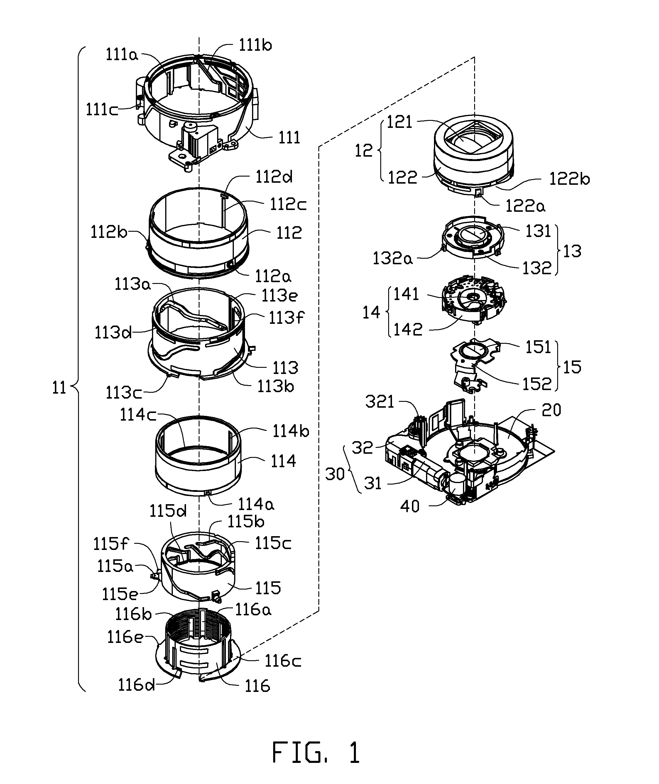
[0022]Referring to FIG. 1 and FIG. 5, an imaging device 100, according to a first exemplary embodiment, includes a zoom lens 10 for capturing images of objects, an image sensing module 20 for sensing the images captures by the zoom lens 10, a first driving unit 30 and a second driving unit 40.

[0023]The zoom lens 10 includes, from an object side to an image side, a lens barrel unit 11, a first lens unit 12, a second lens unit 13, a third lens unit 14 and a fourth lens unit 15. The first lens unit 12, the second lens unit 13, the third lens unit 14 and the fourth lens unit 15 are aligned with each other from the object side to the image side along one optical axis.

[0024]The lens barrel unit 11 includes a fixed barrel 111, a gear barrel 112, an outer guiding barrel 113, a front guiding barrel 114, a cam barrel 115 and an inner guiding barrel 116.

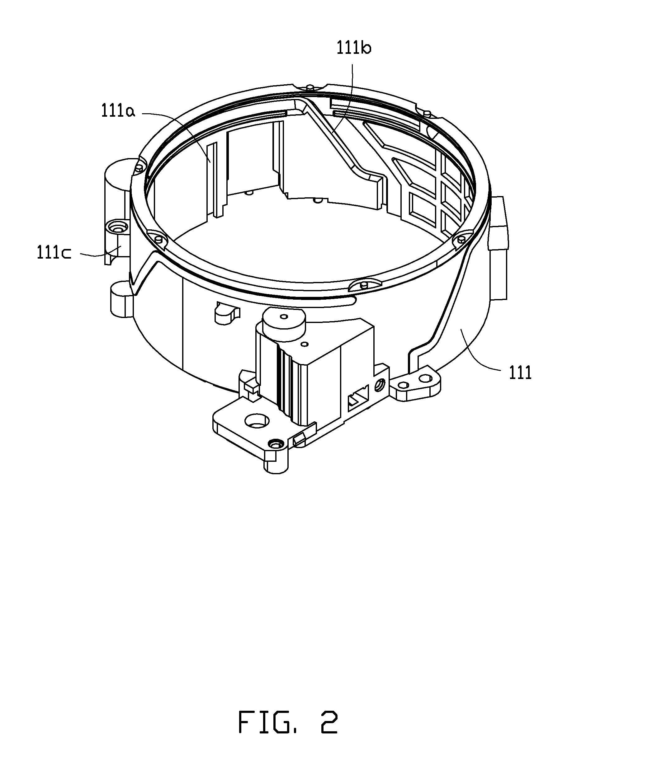
[0025]Referring also to FIG. 2, the fixed ba...


PUM


Abstract

A zoom lens includes a first lens unit, a second lens unit, a third lens unit and a fourth lens unit. The third lens unit includes a movable barrel, a first slidable member able to move in a first direction perpendicular to the optical axis, and a second slidable member able to move along a second direction perpendicular to the optical axis and also perpendicular to the first direction. The movable barrel includes a first Hall member and a first coil, the first slidable member comprises a second Hall member and a second coil. A first magnet is aligned with the first coil, and a second magnet is aligned with the second coil, both coils can be independently energized to compensate any shaking movements experienced by the Hall members.

Description

BACKGROUND[0001]1. Technical Field[0002]The present disclosure relates to zoom lenses and imaging devices, and particularly, relates to a zoom lens and an imaging device with image stabilizing function.[0003]2. Description of Related Art[0004]Many imaging devices, such as digital cameras, digital video cameras, and monitoring devices, have image stabilizing function for correcting image blur due to shaking of the imaging device during shooting.[0005]An imaging device with image stabilizing function will include a shake detecting unit for detecting any shaking of the imaging device, a calculating unit for calculating the degree of the shaking, and a blur correcting unit with a compensating lens for correcting image blur due to the shaking. However, the detecting unit, the calculating unit and the blur correcting unit each have a complicated structure and add to the overall complexity of the imaging device, and increase the overall size of the imaging device.[0006]Therefore, it is des...

Claims


Application Information

Patent Timeline
Patent Type & Authority Applications(United States)
IPC IPC(8): G02B7/10G02B15/14
CPCG02B7/102G02B27/646G02B15/173G02B15/144
Inventor LI, ZI-YUANLI, JUN-JIEZHANG, JIAN-JUNHE, LI-HUITANG, QUAN-LONGKANG, XIAO-TIAN
Owner FOSHAN PREMIER SCI & TECH CO LTD
Learn More