Hydrogen atom model as educational tool
- Summary
- Abstract
- Description
- Claims
- Application Information
AI Technical Summary
Benefits of technology
Problems solved by technology
Method used
Image
Examples
first example
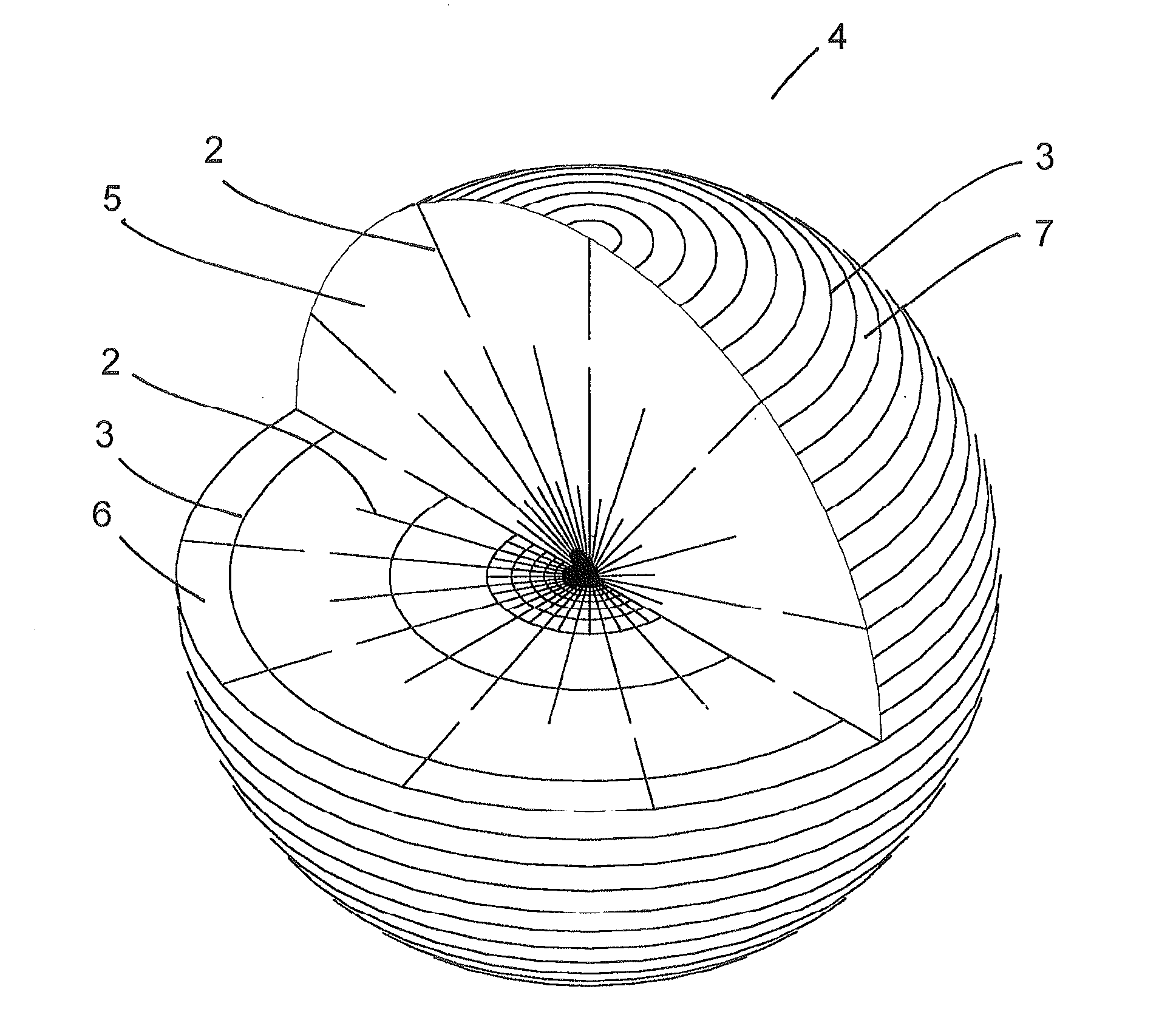
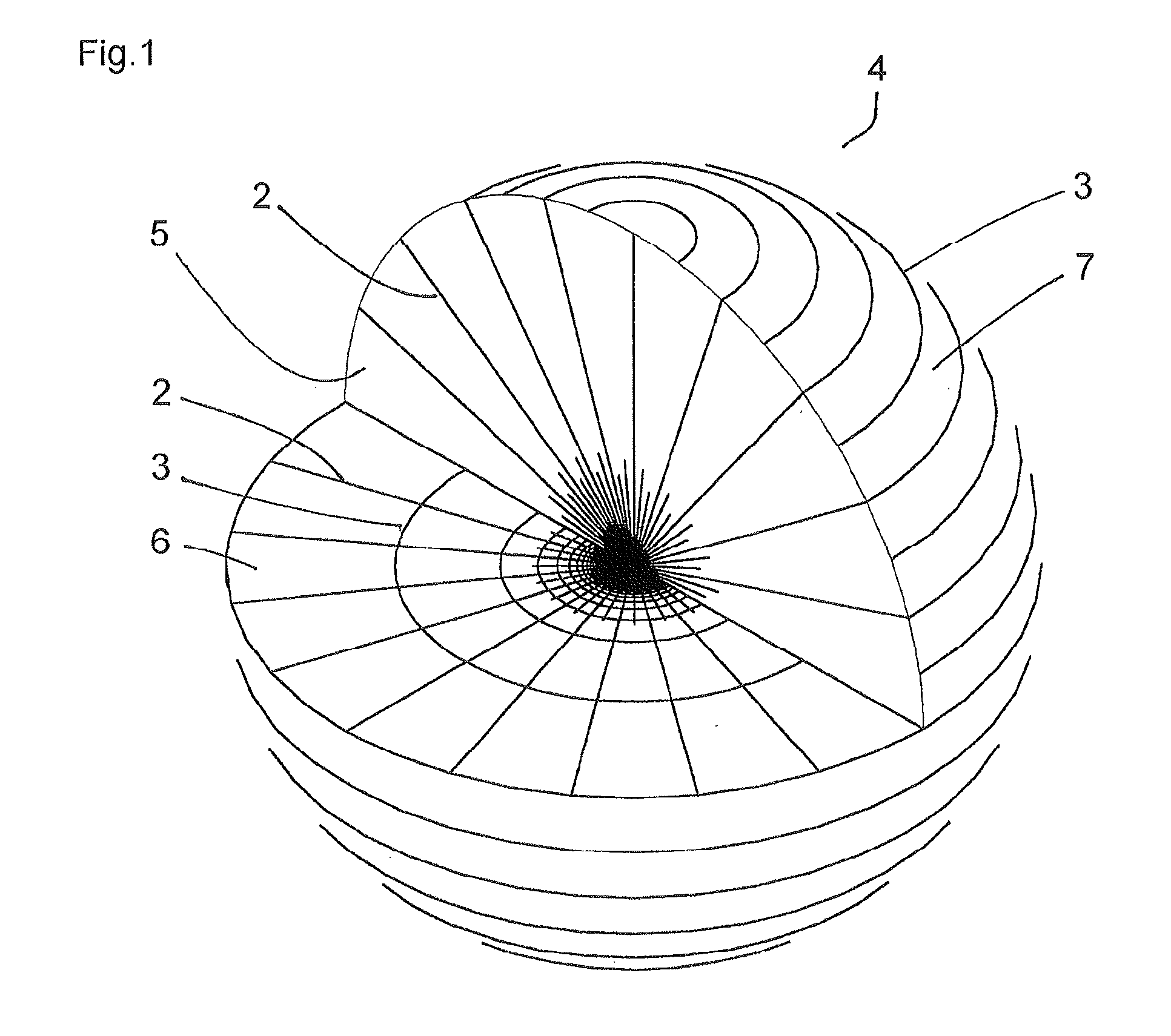
[0024]FIG. 1 illustrates a hydrogen atom model as an educational tool according to the first embodiment of the present invention. Electric field E obtained by a gradient vector operation applied to a wave function of a 1s orbital of a hydrogen atom represented by polar coordinates and shown in formula 1, and a sign inversion to the result of the vector operation is given by formula 6.
E=(1 / a0)exp(−r / a0)ir (6)
A vector iris a unit vector in a direction of r.
[0025]Since the electric field only has an r-component, electric lines of force 2 are expressed by radial straight lines extending outward from the center of the orbital. Magnetic lines of force disclosed in patent document 1 are used for magnetic lines of force 3 as described later. Magnetic lines of force 3 are given by formula 7. In formula 7, difference between magnetic flux density and magnetic field, a coefficient μ0, and the like are neglected, because those factors do not matter with magnetic lines of force 3.
H=(1 / r−1 / a0)ex...
second example
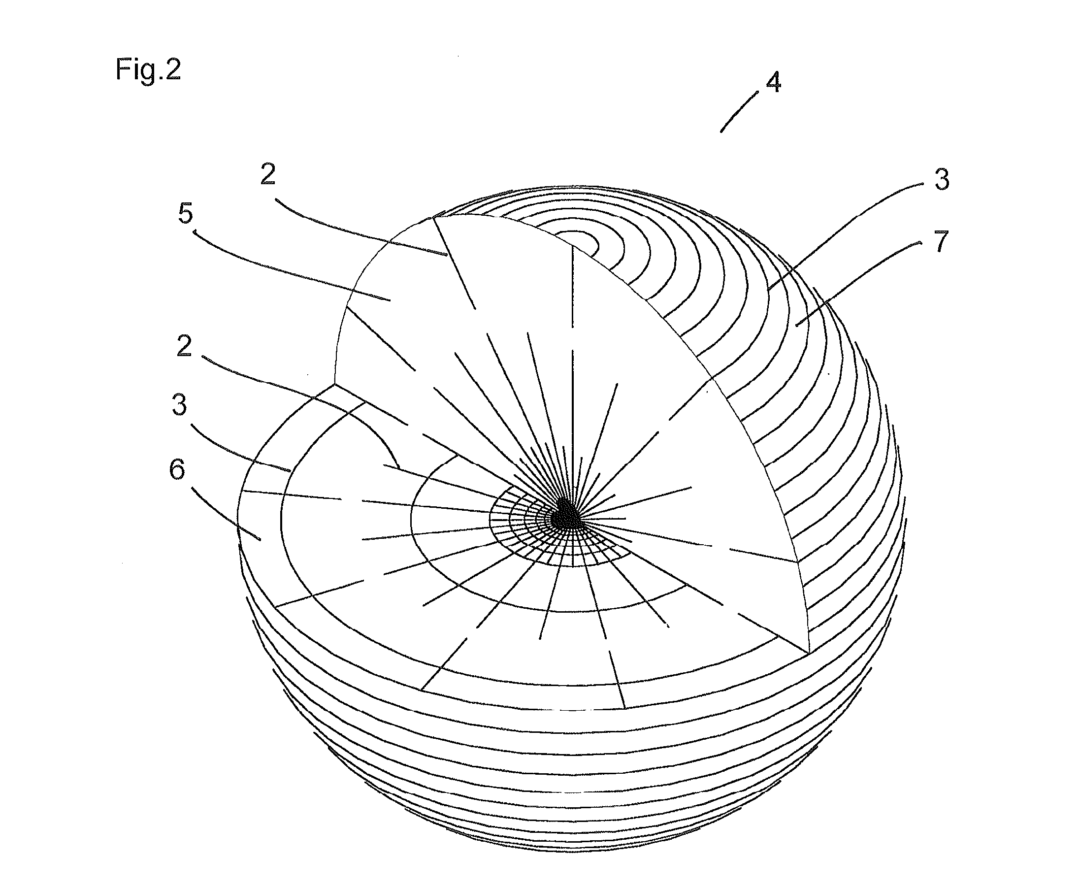
[0026]FIG. 2 illustrates a hydrogen atom model as an educational tool according to the first embodiment of the present invention, and expresses distribution of electric and magnetic fields in a 2s orbital of a hydrogen atom. The electric field shown in formula 8 is obtained by a gradient vector operation applied to a wave function of a 2s orbital represented by polar coordinates and shown in formula 2, and a sign inversion to the result of the vector operation.
E=(1 / a0)(2−r / 2a0)exp(−r / 2a0)ir (8)
The magnetic field of the 2s orbital is given by formula 9.
H=(2 / r−3 / a0+r / a02)exp(−r / 2a0)iφ (9)
FIG. 2 is basically the same as FIG. 1. However, FIG. 2 is different from FIG. 1 in having no electric lines of force 2 drawn, in red for example, in a region of which radius is around r=4a0 either on the vertical plane 5 or horizontal plane 6, because the electric field in a 2s orbital is zero at the radius r=4a0.
third example
[0027]FIG. 3 illustrates a hydrogen atom model as an educational tool according to the second embodiment of the present invention, and expresses electric lines of force 2 of a 2pz orbital drawn on a vertical plane defined by any constant azimuthal angle φ. Electric field E obtained by a gradient vector operation applied to the wave function u100 represented by parabolic coordinates and shown in formula 4, and a sign inversion to the result of the vector operation is given by formula 10.
E={iξ(3−ξ / 2a0)ξ1 / 2+iη(1−ξ / 2a0)η1 / 2}exp{−(ξ+η) / 4a0} / {2a0(ξ+η)1 / 2} (10)
[0028]Here, vectors iξ and iη are unit vectors in directions of ξ and η, respectively. A plurality of electric lines of force 2 within a circular region having a radius of r=6a0 drawn in FIG. 3 are obtained by applying the method disclosed in patent document 2 to formula 10.
PUM
 Abstract
Description
Claims
Application Information
 - R&D
- Intellectual Property
- Life Sciences
- Materials
- Tech Scout
- Unparalleled Data Quality
- Higher Quality Content
- 60% Fewer Hallucinations
Browse by: Latest US Patents, China's latest patents, Technical Efficacy Thesaurus, Application Domain, Technology Topic, Popular Technical Reports.
© 2025 PatSnap. All rights reserved.Legal|Privacy policy|Modern Slavery Act Transparency Statement|Sitemap|About US| Contact US: help@patsnap.com


