
Coding device, decoding device, coding method, and decoding method

a technology of coding device and coding method, applied in the field of coding device, coding device, coding method, and coding method, can solve the problems of difficulty in high-accuracy detection of pitch contour, deterioration of sound quality, and waste of bits to send time warping information, so as to achieve the effect of improving sound quality

Active Publication Date: 2013-06-06
PANASONIC CORP
View PDF4 Cites 7 Cited by
  • Summary
  • Abstract
  • Description
  • Claims
  • Application Information

AI Technical Summary

Benefits of technology

The coding device described in this patent improves sound quality using a small number of bits, even when the audio signal has a large ratio of change. This means that the device can make audio sound better even if it changes frequently.

Problems solved by technology

However, it is difficult to detect the pitch contour with high accuracy because the amplitude and cycle of the audio signal changes.
If a time warping scheme is applied based on an inaccurate pitch contour, the sound quality deteriorates and bits are wasted to send time warping information.
Currently, there is no efficient way to code the pitch contour information in the time warping schemes in the prior arts.
However, in the case where the audio signal has a large pitch change ratio and cannot be covered by the fixed table, the performance of the time warping scheme drops.
As described above, a small fixed table is not sufficient for the situation in which the pitches change dramatically.
This can be costly especially in low bit-rate coding.
Specifically, although coding efficiency can be improved by using a large number of bits when sending the time warping information, bits left for cording the audio signal are not sufficient, which causes deterioration of sound quality.

Method used


Image

  • Coding device, decoding device, coding method, and decoding method
  • Coding device, decoding device, coding method, and decoding method
  • Coding device, decoding device, coding method, and decoding method

Examples


embodiment 1

[0065]In Embodiment 1, a coding device applied with a dynamic time warping scheme is proposed.

[0066]FIG. 8 is a block diagram showing a functional configuration of a coding device 10 according to Embodiment 1 of the present invention.

[0067]As shown in FIG. 8, the coding device 10 is a device which codes an input audio signal that is an audio signal to be inputted, and includes a pitch contour detection unit 101, a dynamic time warping unit 102, a lossless encoder 103, a time warping unit 104, a transform encoder 105, and a multiplexer 106.

[0068]The pitch contour detection unit 101 detects a pitch contour that is information indicating a change in pitch of an input audio signal within a period.

[0069]Specifically, one frame of each of input audio signals of a right channel and a left channel is inputted to the pitch contour detection unit 101. Then, the pitch contour detection unit 101 detects a pitch contour of each of the input audio signals of the right channel and the left channel...

embodiment 2

[0095]In Embodiment 2, a dynamic time warping scheme performed by the coding device 10 is described which includes a scheme for modifying a pitch contour according to the harmonic structures.

[0096]As explained in the above Technical Problem, pitch contour detection is difficult since the amplitude and cycle of the audio signal change. In the case where pitch contour information is directly used for time warping, when a pitch contour is inaccurate, performance of time warping is affected. Since the harmonics of the signal are modified in proportion to pitch shifting during time warping, the effect of time warping on the harmonics has to be taken into consideration.

[0097]In Embodiment 2, a dynamic time warping scheme is proposed. A pitch contour is modified by analyzing harmonic structure, and effective first time warping parameter is generated.

[0098]This dynamic time warping scheme includes three parts. In a first part, the pitch contour is modified according to the harmonic structur...

embodiment 3

[0134]In Embodiment 3, a decoding device applied with the dynamic time warping scheme is proposed. FIG. 13 is a block diagram showing a functional configuration of a decoding device 20 according to Embodiment 3 of the present invention.

[0135]As shown in FIG. 13, the decoding device 20 is a device which decodes a coded audio signal coded by the coding device 10, and includes a lossless decoder 201, a dynamic time warping reconstruction unit 202, a time warping unit 203, a transform decoder 204, and a demultiplexer 205.

[0136]The demultiplexer 205 demultiplexer the input bitstream into the coded time warping parameter, the transform encoder information, and the coded audio signal.

[0137]The bitstream inputted here is the bitstream outputted by the multiplexer 106 of the coding device 10, that is, the bitstream obtained by multiplexing: the coded audio signal; the coded time warping parameter; and the transform encoder information. The coded audio signal is obtained by coding a pitch-cor...


PUM


Abstract

A coding device includes: a pitch contour detection unit which detects a pitch contour of an input audio signal; a dynamic time warping unit which determines the number of pitch nodes based on the pitch contour and generates a first time warping parameter including information indicating the determined number of pitch nodes, a pitch change position, and a pitch change ratio; a first encoder which codes the first time warping parameter; a time warping unit which corrects pitch, using the information obtained from the first time warping parameter, to approximate the pitches of the number of pitch nodes to a predetermined reference value; a second encoder which codes the input audio signal at the corrected pitch; and a multiplexer which multiplexes the coded time warping parameter and the coded audio signal to generate a bitstream.

Description

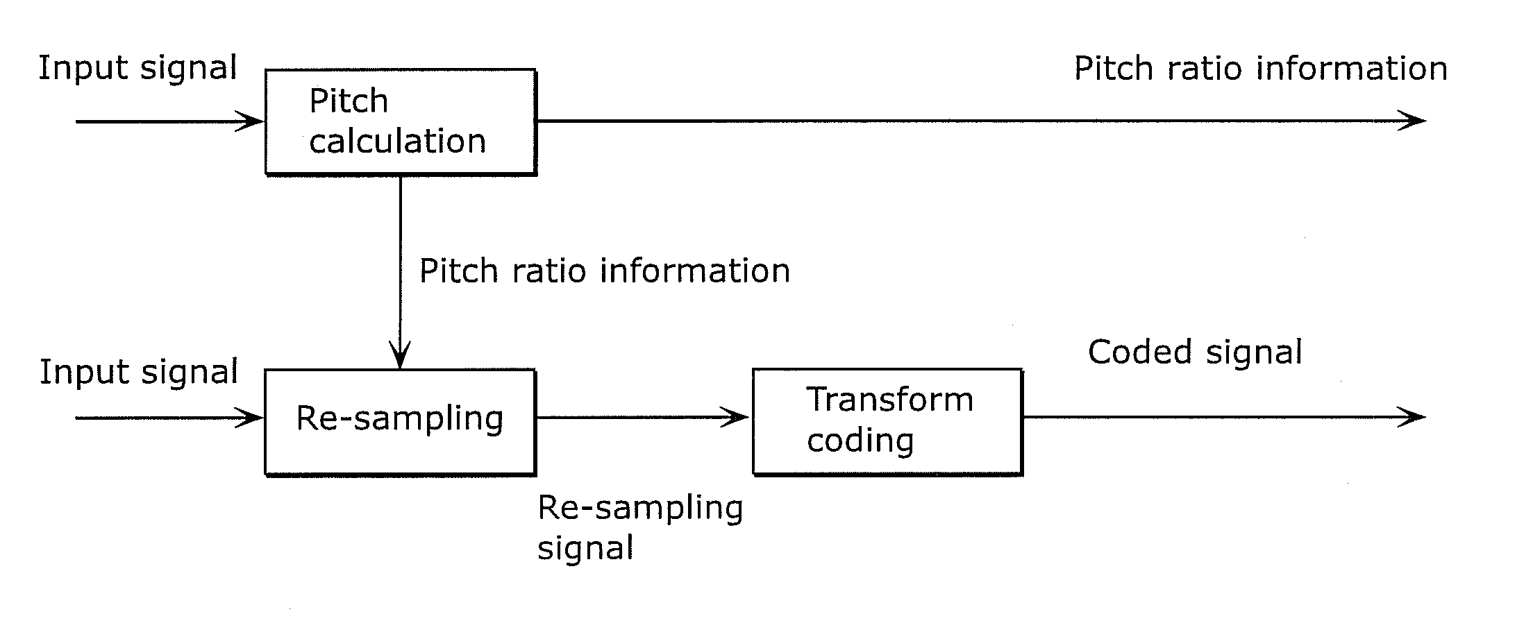
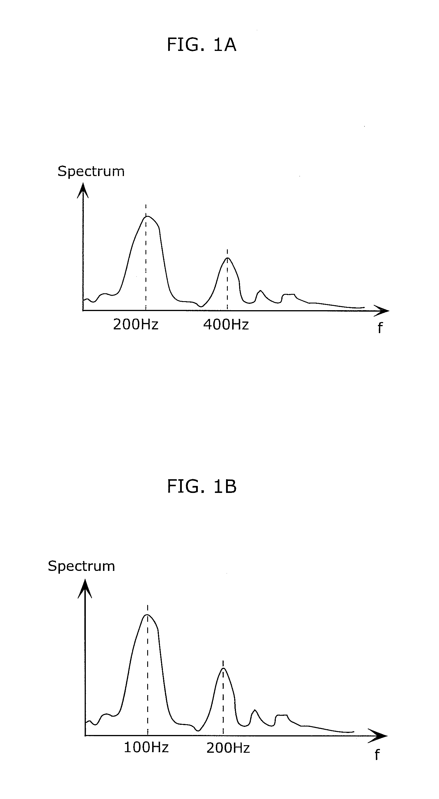
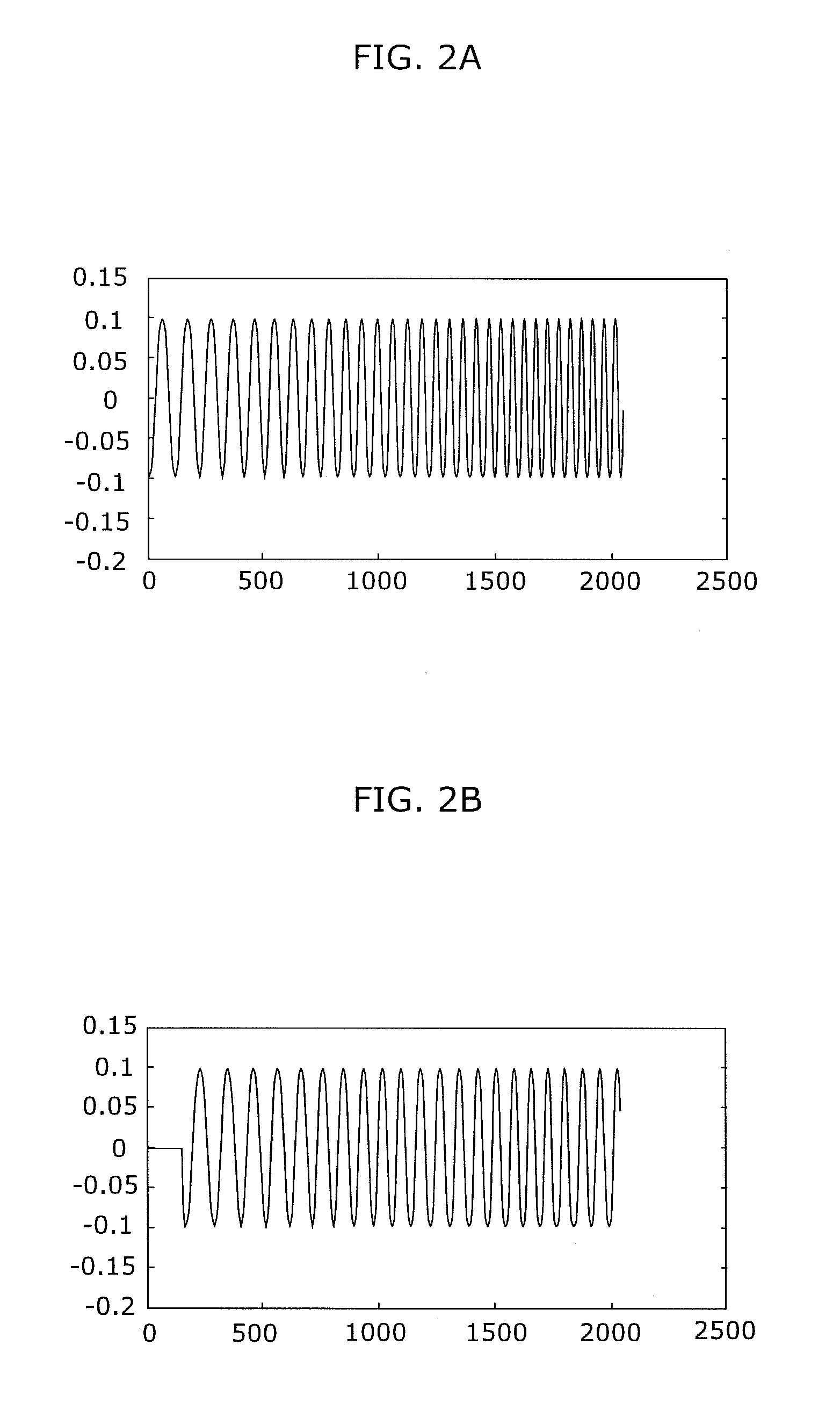
TECHNICAL FIELD[0001]The present invention relates to coding devices, decoding devices, coding methods, and decoding methods for coding inputted audio signals or decoding the coded audio signals.BACKGROUND ART[0002]A coding device is designed to code an audio signal efficiently. In human speech, the fundamental frequency (pitch) of an audio signal changes sometimes. This causes the energy of the audio signal to propagate through wider frequency bands. It is not efficient to code a pitch-changing audio signal by an acoustic signal coding device, especially in a low bit-rate.[0003]Therefore, conventionally, the time warping technology is used to compensate the effect of pitch change (See Patent Literature (PTL) 1 and Non Patent Literature (NPL) 1, for example).[0004]More specifically, the time warping technology is used to achieve pitch correction (pitch shifting). FIGS. 1A and 1B illustrate an example of the conventional scheme of pitch shifting. Specifically, FIG. 1A shows a spectru...

Claims


Application Information

Patent Timeline
Patent Type & Authority Applications(United States)
IPC IPC(8): G10L25/90G10L19/02G10L19/09G10L19/26
CPCG10L19/09G10L19/265G10L2025/906G10L19/0212G10L19/26G10L25/90G10L19/00G10L19/008G10L19/02G10L19/04G10L19/06G10L19/07G10L19/08G10L21/00
Inventor ISHIKAWA, TOMOKAZUNORIMATSU, TAKESHIZHONG, HAISHANZHAO, DANCHONG, KOK SENG
Owner PANASONIC CORP
Learn More