Manually Operable Gas Regulator

Active Publication Date: 2013-06-13
HSIAO CHENG SHENG
View PDF12 Cites 10 Cited by
  • Summary
  • Abstract
  • Description
  • Claims
  • Application Information

AI Technical Summary

Benefits of technology

[0005]The primary objective of the present invention is to provide a manually operable gas regulator to ac

Problems solved by technology

However, the gas regulator of FIG. 4 can not be manually operat

Method used


Image

  • Manually Operable Gas Regulator
  • Manually Operable Gas Regulator
  • Manually Operable Gas Regulator

Examples


Embodiment Construction

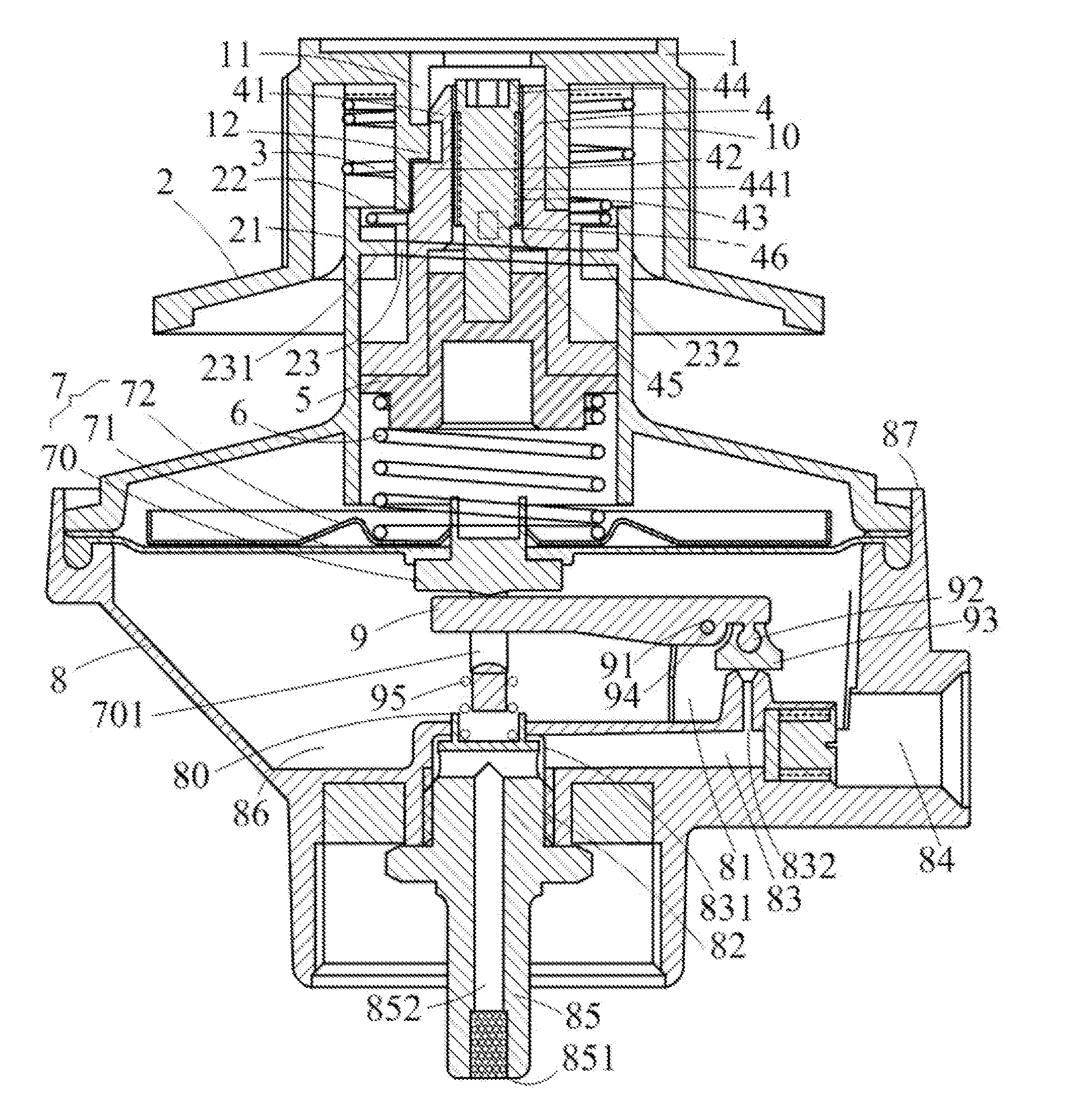
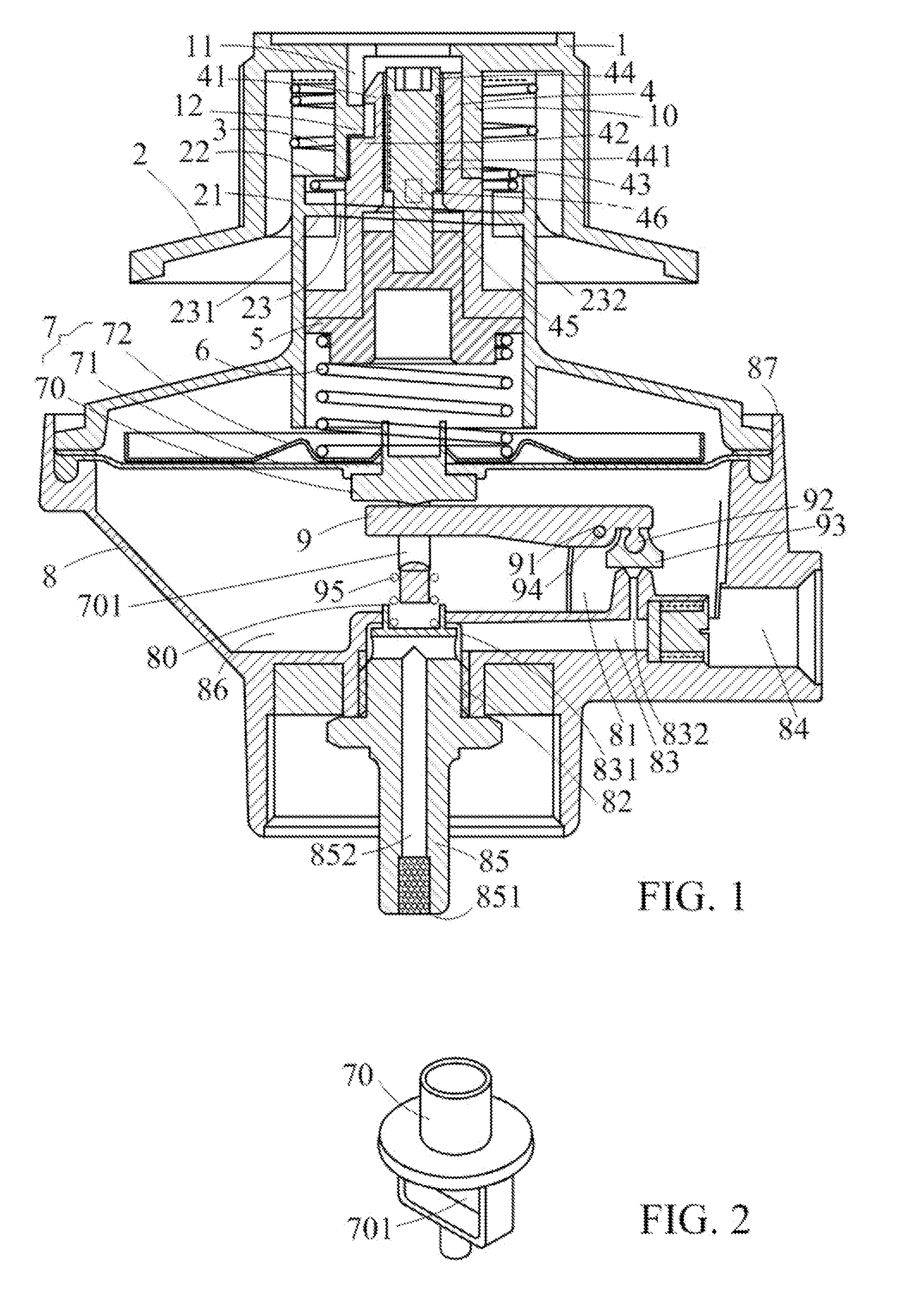
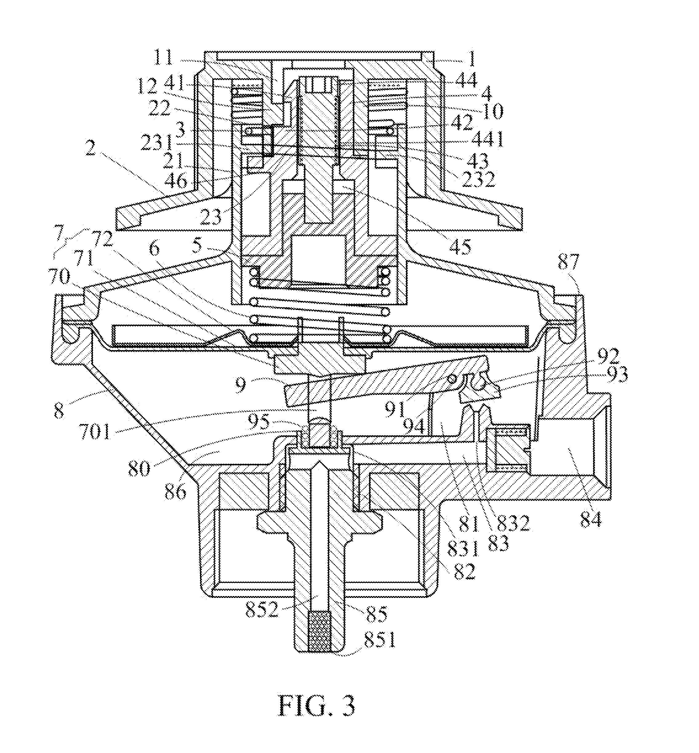
[0015]With reference to FIGS. 1-3, a manually operable gas regulator according to the present invention includes a knob 1 having an inner tube 10. An engagement groove 11 is formed in an inner periphery of the inner tube 10. A protrusion 12 is formed on a mediate section of the engagement groove 11. An upper cover 2 includes a circular tube 21 having two open ends. A circular hole 22 is formed in an upper end of the circular tube 21. A semi-circular, inclined slope 23 is formed on an inner periphery of the circular tube 21 and has an upper stop end 231 and a lower stop end 232. A return spring 3 has two ends respectively abutting the knob 1 and the upper cover 2. Thus, the knob 1 can be returned to its initial position by the return spring 3 when external force acting on the knob 1 vanishes.

[0016]A hollow rotating block 4 includes an engagement portion 41 having a width equal to a width of the engagement groove 11 of the knob 1. The engagement portion 41 is engaged with the engageme...


PUM


Abstract

A manually operable gas regulator includes a knob, an upper cover, a return spring, a movable block, a pressure adjusting spring, a diaphragm assembly, a body, and a lever pivotably mounted to the body. An upper end of the diaphragm assembly abuts a lower end of the pressure adjusting spring whose upper end abuts a lower end of the movable block. An upper end of the movable block abuts a lower end of the movable block securely engaged with the upper cover and the knob. Rotation of the knob causes upward/downward movement of an axle of the diaphragm assembly to pivot the lever. A plug on an end of the lever is moved to accurately control the flow of gas and to accurately close or open an output end of an inlet passage of the body.

Description

BACKGROUND OF THE INVENTION[0001]The present invention relates to a gas regulator and, more particularly, to a gas regulator for controlling flow of gas.[0002]FIG. 4 shows a conventional gas regulator including a pressure adjusting cap 1′, an upper cover 2′, a screw rod 3′, a pressure adjusting block 4′, a spring 5′, a diaphragm assembly 6′, a lever 7′, a base spring 8′, and a body 9′. A fastener 12′ is extended through a hole 11′ in an upper end of the pressure adjusting cap 1′ and engaged with a screw hole 31′ of the screw rod 3′. The upper cap 2′ includes a circular hole 21′, an exhaust 22′, and a plurality of longitudinal passageways 23′. The screw rod 3′ includes a head 30′ extending beyond the circular hole 21′. The exhaust 22′ is in communication with an interior of the upper cover 2′ to allow passage of air into or out of the upper cover 2′. The pressure adjusting block 4′ is movably received in and limited by the passageways 23′ defined in an inner periphery of the upper co...

Claims


Application Information

Patent Timeline
IPC IPC(8): F16K31/12
CPCG05D16/0691Y10T137/7782Y10T137/782Y10T137/7823Y10T137/783Y10T137/7831
Inventor HSIAO, CHENG-SHENG
Owner HSIAO CHENG SHENG
Why Eureka
Try Eureka