Rolling cutter with improved rolling efficiency

a cutter and rolling technology, applied in cutting machines, earthwork drilling and mining, construction, etc., can solve problems such as cutter failure, drill bit failure, cutter failure during drilling operations, and bit and pdc cutters being subjected to substantial abrasive forces

Inactive Publication Date: 2013-06-13
SMITH INT INC
View PDF10 Cites 61 Cited by
  • Summary
  • Abstract
  • Description
  • Claims
  • Application Information

AI Technical Summary

Problems solved by technology

Additionally, the bit and the PDC cutters may be subjected to substantial abrasive forces.
In some instances, impact, vibration, and erosive forces have caused drill bit failure due to loss of one or more cutters, or due to breakage of the blades.
Without proper flow characteristics, insufficient cooling of the cutters 250 may result in cutter failure during drilling operations.
Specifically, alloys suitable for brazing cutting elements with diamond layers thereon have been limited to only a couple of alloys which offer low enough brazing temperatures to avoid damage to the diamond layer and high enough braze strength to retain cutting elements on drill bits.
Conventional polycrystalline diamond is stable at temperatures of up to 700-750° C. in air, above which observed increases in temperature may result in permanent damage to and structural failure of polycrystalline diamond.
Upon heating of polycrystalline diamond, the cobalt and the diamond lattice will expand at different rates, which may cause cracks to form in the diamond lattice structure and result in deterioration of the polycrystalline diamond.
Damage may also be due to graphite formation at diamond-diamond necks leading to loss of microstructural integrity and strength loss, at extremely high temperatures.
Exposure to heat (through brazing or through frictional heat generated from the contact of the cutter with the formation) can cause thermal damage to the diamond table and eventually result in the formation of cracks (due to differences in thermal expansion coefficients) which can lead to spalling of the polycrystalline diamond layer, delamination between the polycrystalline diamond and substrate, and conversion of the diamond back into graphite causing rapid abrasive wear.
As a cutting element contacts the formation, a wear flat develops and frictional heat is induced.
As the cutting element is continued to be used, the wear flat will increase in size and further induce frictional heat.
The heat may build-up that may cause failure of the cutting element due to thermal mis-match between diamond and catalyst discussed above.

Method used


Image

  • Rolling cutter with improved rolling efficiency
  • Rolling cutter with improved rolling efficiency
  • Rolling cutter with improved rolling efficiency

Examples


Embodiment Construction

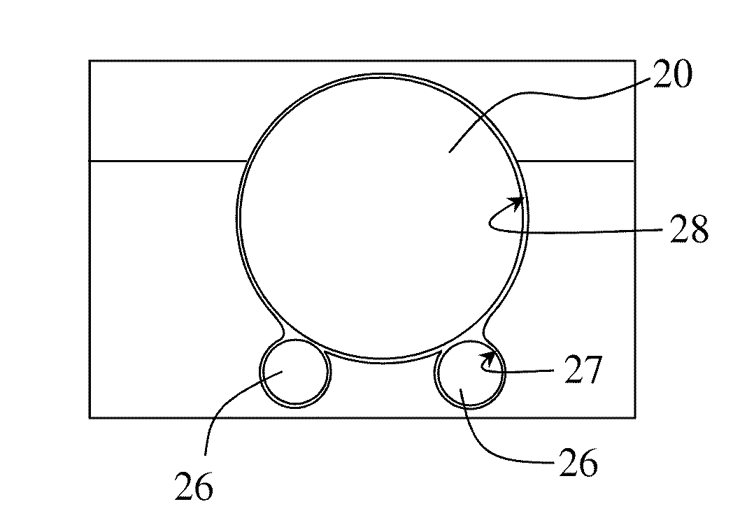
[0041]In one aspect, embodiments disclosed herein relate to polycrystalline diamond compact cutters having improved rolling efficiency, i.e., its ability to rotate freely and easily about its longitudinal axis. The cutting elements may be retained on a bit or tool in any manner such that it is free to rotate about its longitudinal axis. Improved rolling efficiency may be obtained by reducing the contact surface area between the rotatable cutting element and the cutter pocket or sleeve in which is free to rotate. Such reduction in contact surface area may be achieved by reducing the contact surface area along the circumferential side surface of the rotatable cutter and / or a bottom face of the rotatable cutter. Reduction in surface area may include at least one line contact along a circumferential side surface and / or at least one point contact at a bottom face.

[0042]FIGS. 2 and 3 illustrate two different cross-sectional views of a cutting element according to embodiments of the presen...


PUM


Abstract

A cutting structure may include an outer support element; and an inner rotatable cutting element comprising a cutting surface at its upper end; wherein the inner rotatable cutting element comprises at least one line contact along a circumferential side surface thereof and / or at least one point contact at a bottom face thereof.

Description

CROSS-REFERENCE TO RELATED APPLICATIONS[0001]This patent application claims priority to U.S. Provisional Patent Application No. 61 / 559,423, filed on Nov. 14, 2011, which is incorporated herein by reference in its entirety.BACKGROUND[0002]1. Technical Field[0003]Embodiments disclosed herein relate generally to polycrystalline diamond compact cutters and bits or other cutting tools incorporating the same. More particularly, embodiments disclosed herein relate to rolling cutters having reduced contact surfaces and bits or other cutting tools incorporating the same.[0004]2. Background Art[0005]Various types and shapes of earth boring bits are used in various applications in the earth drilling industry. Earth boring bits have bit bodies which include various features such as a core, blades, and cutter pockets that extend into the bit body or roller cones mounted on a bit body, for example. Depending on the application / formation to be drilled, the appropriate type of drill bit may be sele...

Claims


Application Information

Patent Timeline
Patent Type & Authority Applications(United States)
IPC IPC(8): E21B10/50E21B10/08
CPCE21B10/50E21B10/55E21B10/08E21B10/62E21B10/627E21B10/633
Inventor ZHANG, YOUHESHEN, YUELINBURHAN, YURIHAUGVALDSTAD, KJELL
Owner SMITH INT INC
Why Eureka
Try Eureka