

Liquid-sealed vibration isolation device and vibration isolation unit
- Summary
- Abstract
- Description
- Claims
- Application Information
AI Technical Summary
Benefits of technology
Problems solved by technology
Method used
Image

Examples
Embodiment Construction
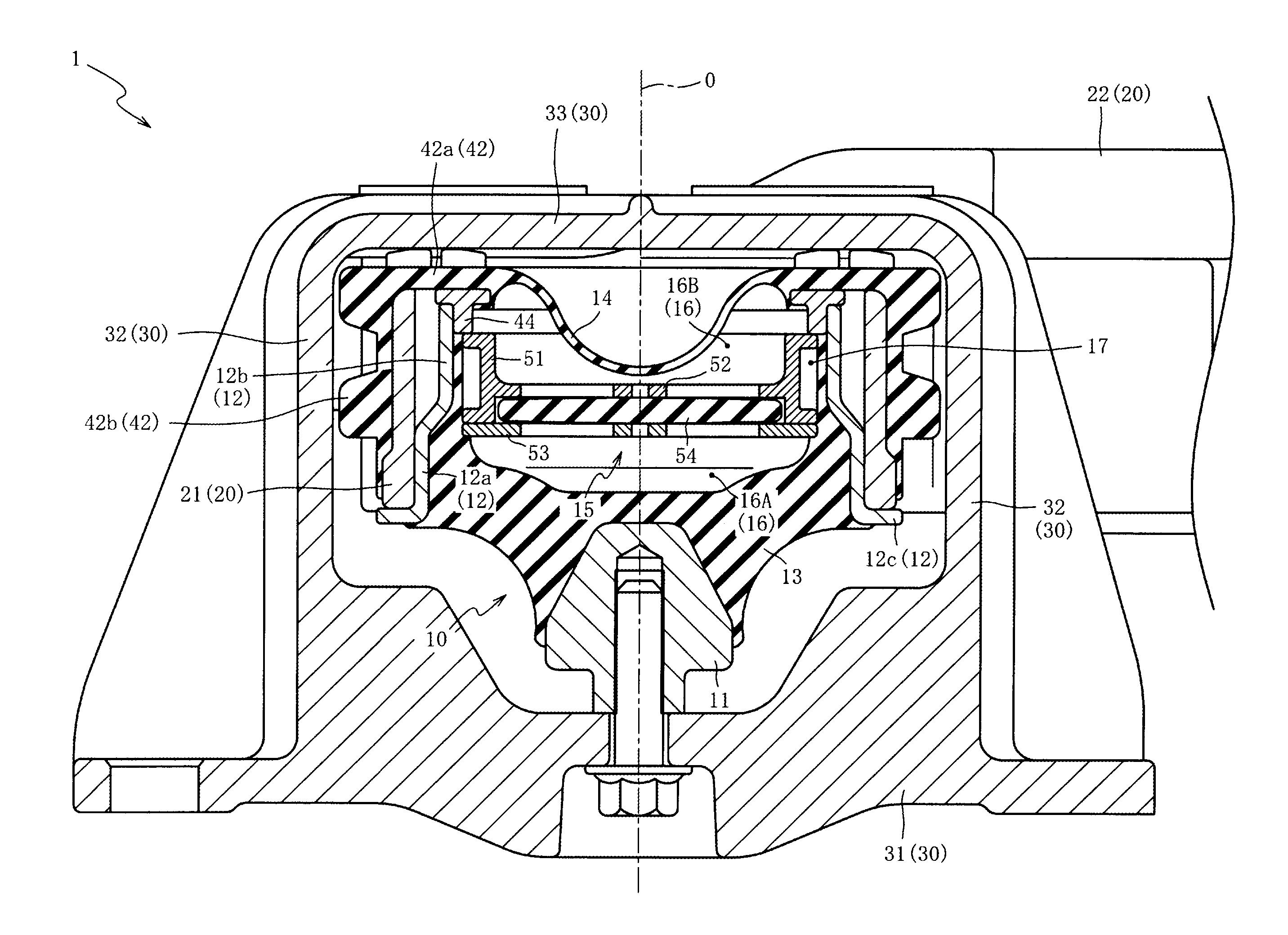
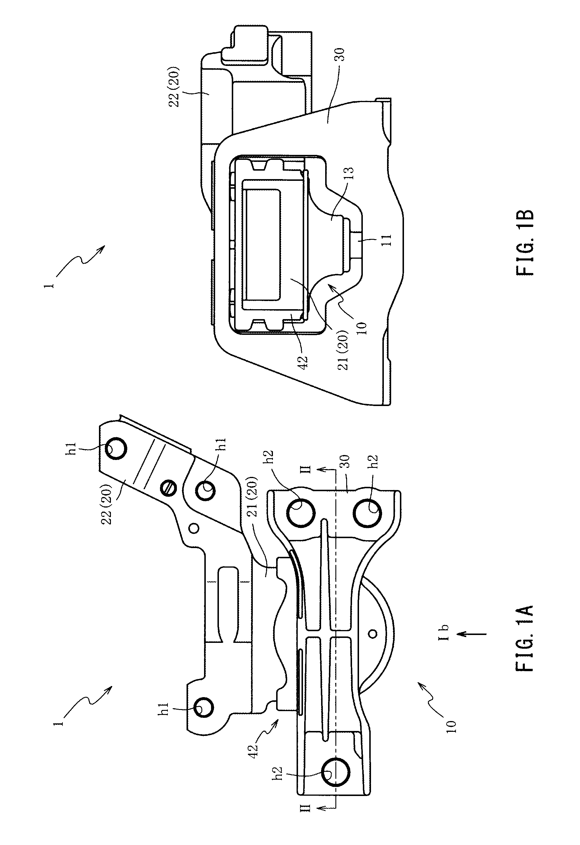
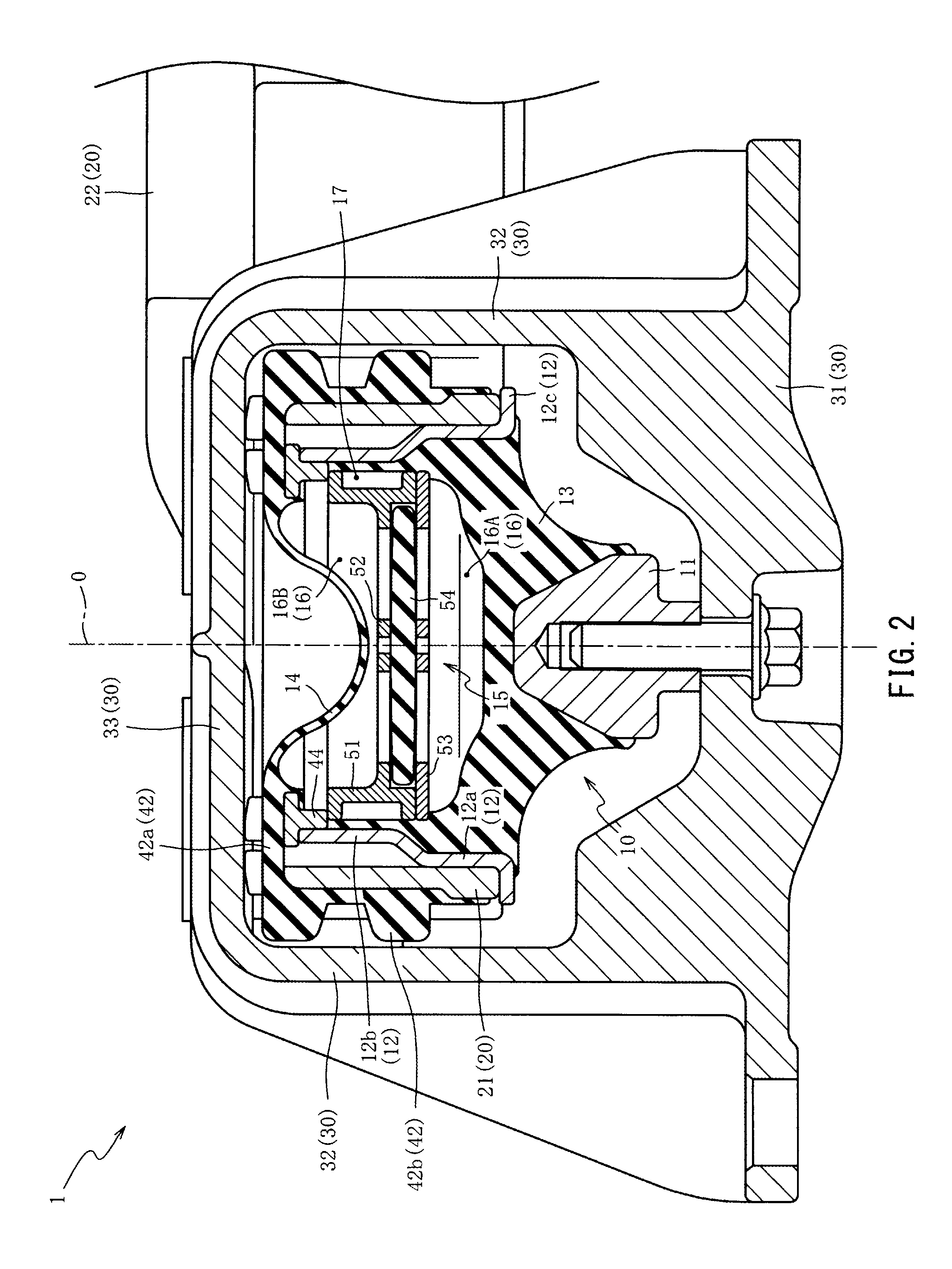
[0032]Hereinafter, the preferred examples of the present invention will be described referring to the attached drawings. First, the overall constitution of a vibration isolation unit 1 will be described referring to FIG. 1A, FIG. 1B and FIG. 2.
[0033]FIG. 1A is a top view of the vibration isolation unit 1 of a first embodiment of the present invention, and FIG. 1B is a front view of the vibration isolation unit 1 when viewed from the direction of the arrow Ib of FIG. 1A. FIG. 2 is a cross-sectional view of the vibration isolation unit 1 taken from the line II-II of FIG. 1A. Further, FIG. 2 corresponds to a cross section including the axis O. Furthermore, in FIG. 2, a bolt is illustrated not by the cross-sectional view.
[0034]As shown in FIG. 1A, FIG. 1B and FIG. 2, the vibration isolation unit 1 is a device for suppressing vibration of an engine (not shown) of an automobile from being transmitted to a vehicle body (not shown) while supporting and fixing the engine, and includes a vibr...
PUM
 Abstract
Description
Claims
Application Information