Radiation detector

a detector and radiation technology, applied in the field of radiation detectors, can solve the problems of increasing the cost of lithium glass, increasing the cost of lithium iodide, and the scintillation efficiency of lithium glass is not as high as that of lithium iodide, and achieve the effect of detecting incident neutrons more efficiently

Active Publication Date: 2013-06-13
SYMETRICA
View PDF2 Cites 13 Cited by
  • Summary
  • Abstract
  • Description
  • Claims
  • Application Information

AI Technical Summary

Benefits of technology

The technology described in this patent involves adding a layer of material that helps filter out certain types of particles called neutons before they interact with another substance. This makes it easier for researchers to detect these particles accurately.

Problems solved by technology

The technical problem addressed in this patent is the development of new techniques for detecting neutroons while being insensitive to gamma rays, allowing for larger and lower cost detectors to be utilized. Current options like helium-3 based detectors are limited in availability and require higher costs due to the increasing demand for these elements. Alternative technology solutions are desired to address issues related to the detection of nuclides emitted through slow neutron capture.

Method used


Image

  • Radiation detector
  • Radiation detector
  • Radiation detector

Examples


Embodiment Construction

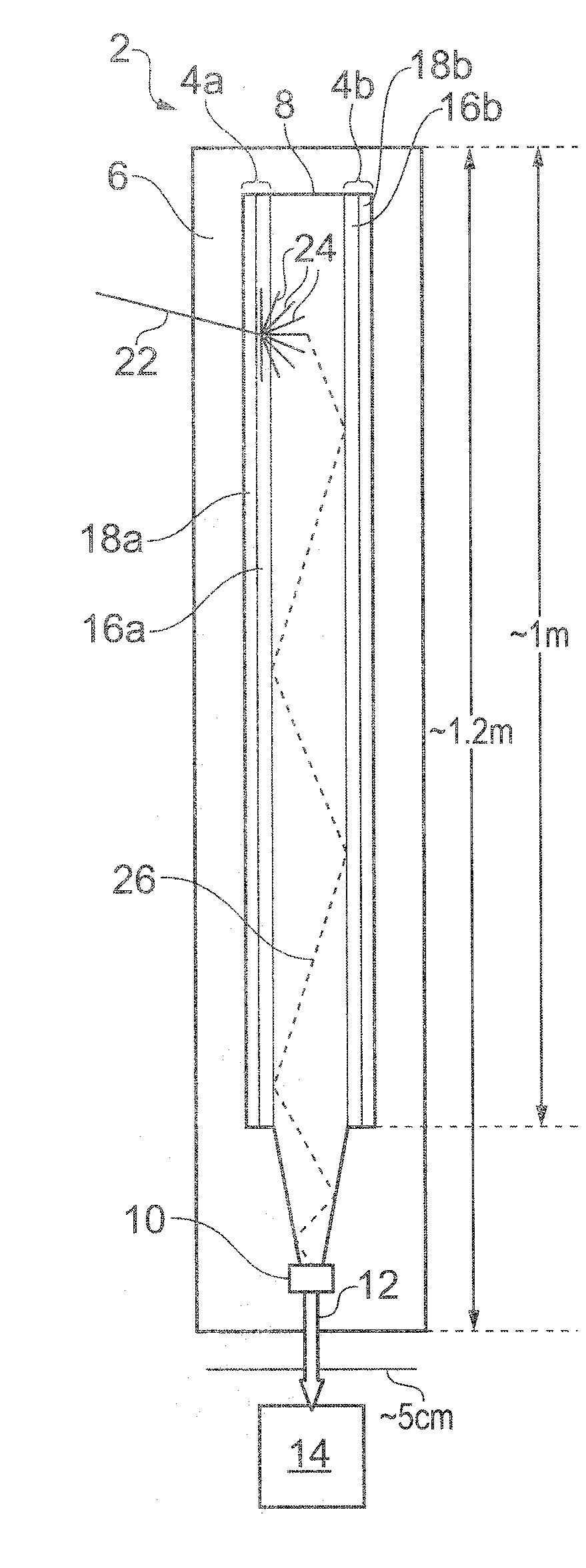
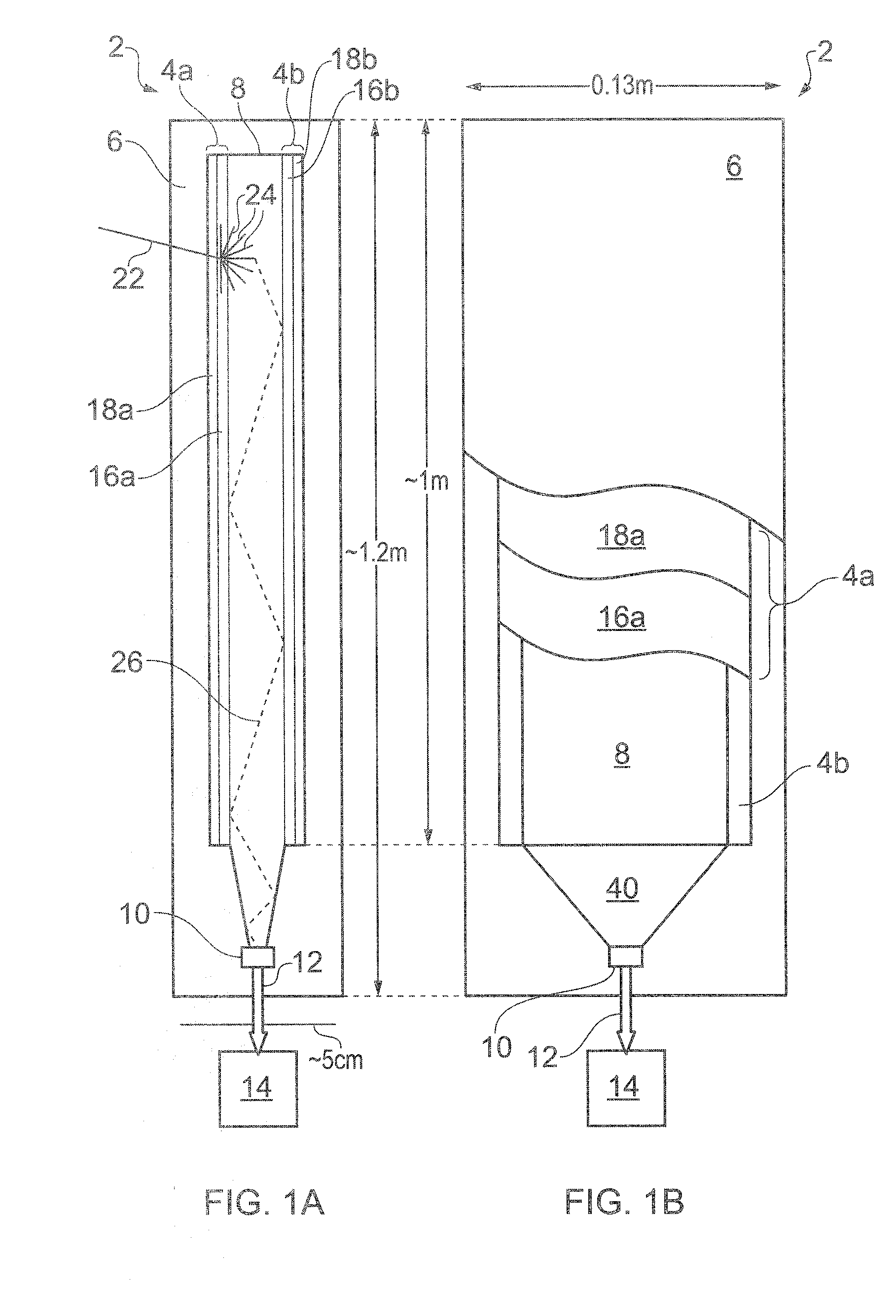
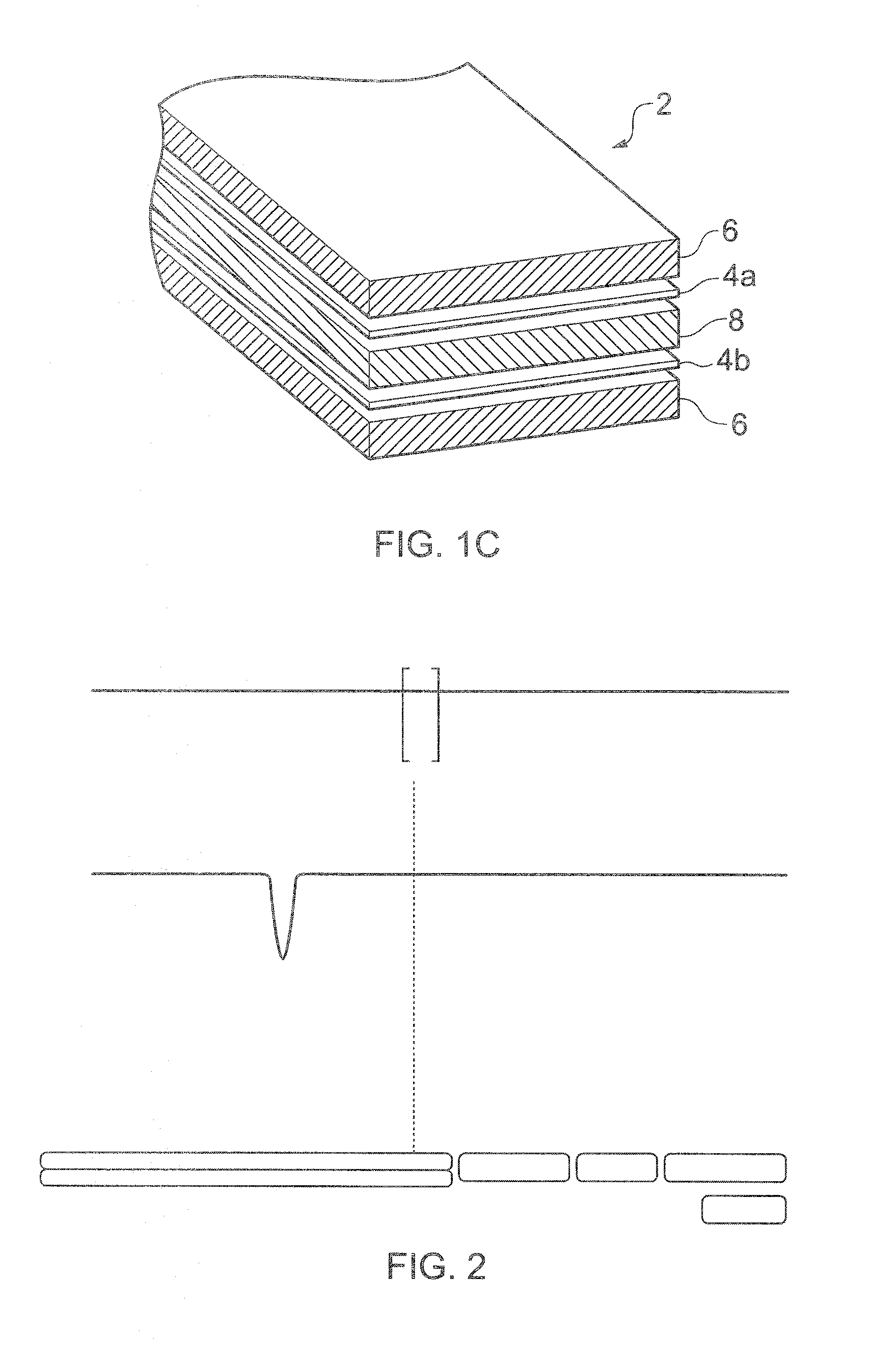
[0048]FIGS. 1A, 1B and 1C schematically show a neutron detector 2 according to an embodiment of the invention in respective side, face and perspective views. The neutron detector 2 has a generally layered structure and is shown in FIGS. 1B and 1C in partial cut-away to reveal features of the different layers. The face view of FIG. 1B is from the left-hand side of the detector as shown in FIG. 1A, although this is not overly significant since in this example embodiment the detector is in any case symmetric about the plane of the drawing of FIG. 1B. Various layers of the detector 2 and schematically shown separated form one another in FIG. 1C for ease of representation. In practice the different layers will be directly adjacent one another.

[0049]The neutron detector comprises a pair of neutron absorbing conversion screens 4a, 4b arranged on either side of a wavelength-shifting light-guide 8 in the form of a plastic scintillator plank. The light-guide 8 is coupled to a photodetector 10...


PUM


Abstract

A radiation detector for neutrons and gamma-rays is described. The detector includes a conversion screen (4a) comprising a mixture of a neutron absorbing material, e.g. containing 6Li, and a phosphorescent material, e.g. ZnS(Ag) and a wavelength-shifting light-guide (8) arranged to receive photons emitted from the phosphorescent material and generate wavelength-shifted photons therefrom. The wavelength-shifting light-guide is doped so as to form a gamma-ray scintillator material operable to generate scintillation photons in response to a gamma-ray detection event therein. A photodetector (10) is optically coupled to the wavelength-shifting light-guide and arranged to detect the wavelength-shifted photons and the scintillation photons. Signals from the photodetector are processed to distinguish neutron detection events from gamma ray detection events.

Description


Claims


Application Information

Patent Timeline
Owner SYMETRICA
Why Eureka
Try Eureka