Illumination device and projector
a technology of projection device and projector, which is applied in the direction of picture reproducers, picture reproducers using projection devices, instruments, etc., can solve the problems of difficult manufacturing and control of the operation of deformable mirrors, and achieve the effect of high light use efficiency and efficient production
- Summary
- Abstract
- Description
- Claims
- Application Information
AI Technical Summary
Benefits of technology
Problems solved by technology
Method used
Image
Examples
first embodiment
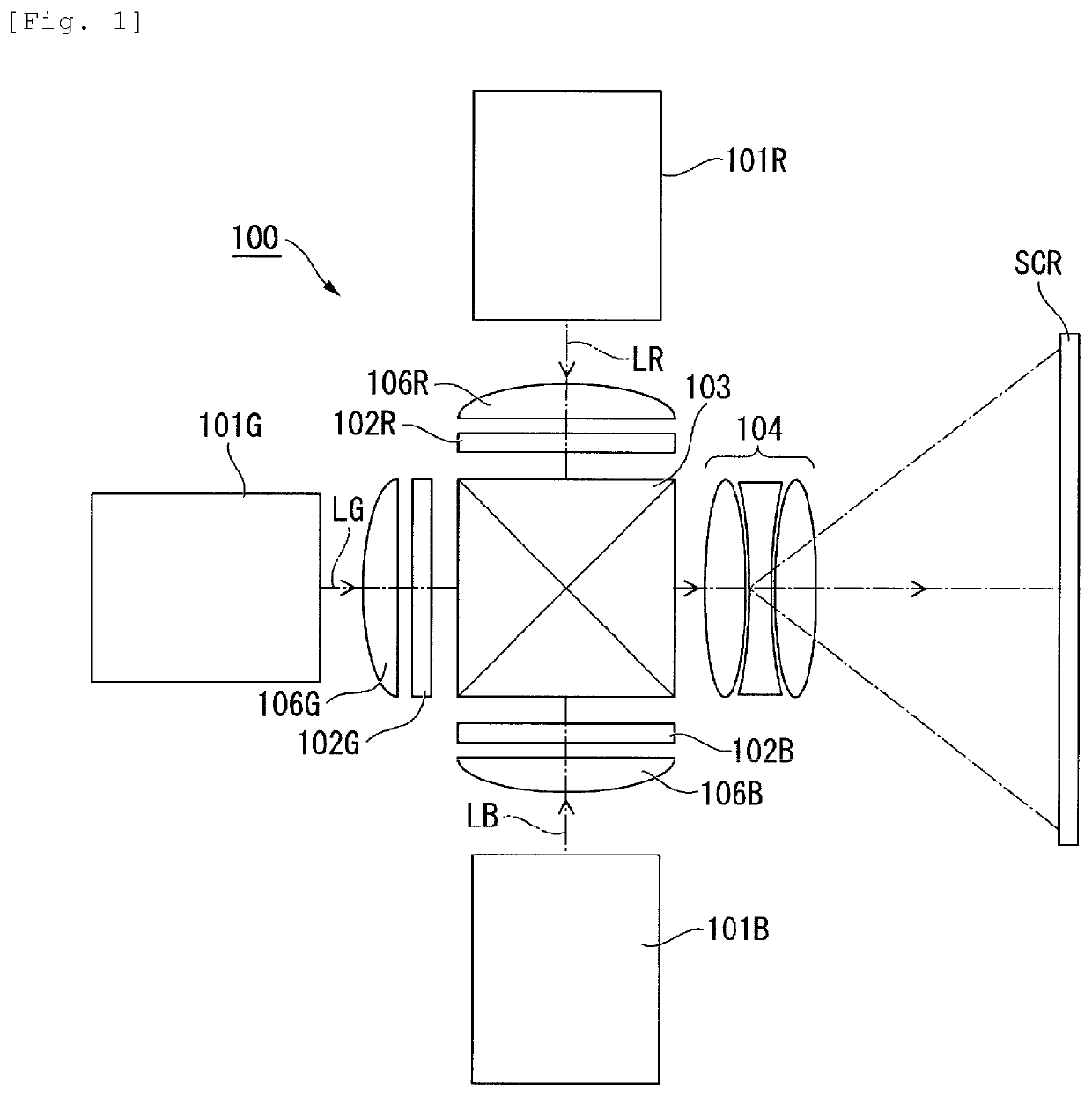
[0030]FIG. 1 is a schematic configuration diagram showing a projector in an embodiment.
[0031]As shown in FIG. 1, a projector 100 includes an illumination device for red light 101R, an illumination device for green light 101G, an illumination device for blue light 101B, a liquid-crystal light valve for red light 102R, a liquid-crystal light valve for green light 102G, a liquid-crystal light valve for blue light 102B, field lenses 106B, 106G, and 106R, a color synthesizing element 103, and a projection optical system 104.
[0032]In this embodiment, each of the illumination device for red light 101R, the illumination device for green light 101G, and the illumination device for blue light 101B corresponds to the “illumination device” in the claims. Each of the liquid-crystal light valve for red light 102R, the liquid-crystal light valve for green light 102G, and the liquid-crystal light valve for blue light 102B corresponds to the “light modulating device” in the claims.
[0033]The projecto...
second embodiment
[0074]Subsequently, an illumination device according to a second embodiment is explained. In this embodiment as well, only an illumination device for blue light is explained. Explanation is omitted concerning an illumination device for red light and an illumination device for green light. Note that components and members common to the first embodiment are denoted by the same reference numerals and signs. Explanation of the components and the members is omitted or simplified.
[0075]FIG. 6 is a diagram showing a schematic configuration of an illumination device for blue light 201B according to this embodiment.
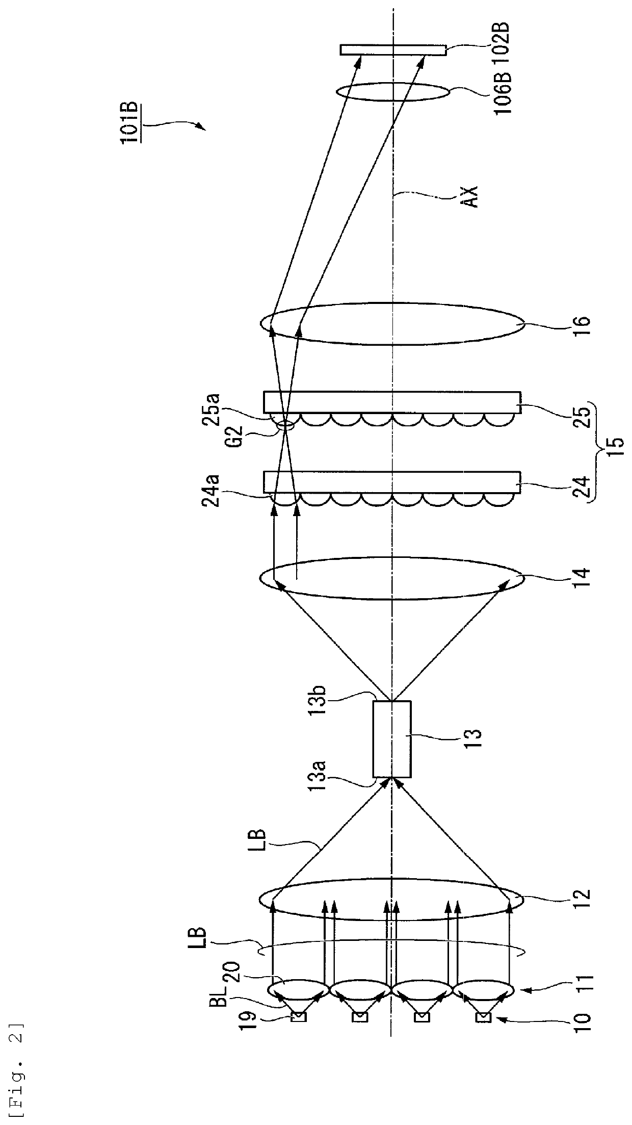
[0076]As shown in FIG. 6, the illumination device for blue light 201B includes the light source device 10, the first collimate optical system 11, the condensing optical system 12, a rod 113, the second collimate optical system 14, the lens integrator 15, and the superimposing lens 16.
[0077]The rod 113 includes a light-incident end face 113a, a light-emitting end face 113b, and a d...
third embodiment
[0080]Subsequently, an illumination device according to a third embodiment is explained. In this embodiment as well, only an illumination device for blue light is explained. Explanation is omitted concerning an illumination device for red light and an illumination device for green light. Note that components and members common to the second embodiment are denoted by the same reference numerals and signs. Explanation of the components and the members is omitted or simplified.
[0081]FIG. 8 is a diagram showing a schematic configuration of an illumination device for blue light 301B according to this embodiment.
[0082]As shown in FIG. 8, the illumination device for blue light 301B includes the light source device 10, the first collimate optical system 11, the condensing optical system 12, a diffusion plate 18, the rod 113, the second collimate optical system 14, the lens integrator 15, and the superimposing lens 16.
[0083]That is, the illumination device for blue light 301B in this embodim...
PUM
 Abstract
Description
Claims
Application Information
 - R&D
- Intellectual Property
- Life Sciences
- Materials
- Tech Scout
- Unparalleled Data Quality
- Higher Quality Content
- 60% Fewer Hallucinations
Browse by: Latest US Patents, China's latest patents, Technical Efficacy Thesaurus, Application Domain, Technology Topic, Popular Technical Reports.
© 2025 PatSnap. All rights reserved.Legal|Privacy policy|Modern Slavery Act Transparency Statement|Sitemap|About US| Contact US: help@patsnap.com


