Radiographic image capturing system and radiographic image capturing method

a radiographic image and imaging system technology, applied in the direction of material analysis using wave/particle radiation, instruments, applications, etc., can solve the problems of field-emission radiation sources that cannot capture radiation images, small radiation dose, and difficulty in preparing an appropriate external power supply, so as to achieve effective radiographic image capture and easy enlarged radiation radiation range

Active Publication Date: 2014-07-01
FUJIFILM CORP
View PDF11 Cites 11 Cited by
  • Summary
  • Abstract
  • Description
  • Claims
  • Application Information

AI Technical Summary

Benefits of technology

[0009]As long as a subject is irradiated with an optimum dose (exposure dose) of radiation depending on the subject, a radiographic image of the subject can be captured based on an exposure dose that is large enough for a doctor to read the resultant radiation image correctly, and the subject remains free of undue radiation exposure.
[0011]An object of the present invention is to provide a radiographic image capturing system and a radiographic image capturing method, which are capable of easily increasing an irradiation range of radiation, and of applying an optimum dose of radiation to a subject, in the case that a radiographic image of the subject is captured using a field-emission radiation source at a short SID.
[0024]Accordingly, with the present invention, even if image capturing (the first and second image capturing processes) of a radiographic image is carried out with respect to the subject at a short SID using field-emission radiation sources, the irradiation range of the radiation can easily be enlarged, and radiation can be applied at an optimum radiation dose (exposure dose) with respect to the subject.
[0025]In the present invention, in a case that the radiation output device and the radiation detecting device face each other, the radiation output device houses therein the at least two radiation sources arranged in a linear array, or at least three radiation sources arranged in a two-dimensional matrix with respect to an irradiated surface of the radiation detecting device that is irradiated with radiation. In this case, capturing of radiographic images can be carried out effectively with respect to any type of region to be imaged.
[0035]Accordingly, with the second invention, even if image capturing of a radiographic image (the aforementioned main exposure process) is carried out with respect to the subject at a short SID using field-emission radiation sources, the irradiation range of the radiation can easily be enlarged, and radiation can be applied at an optimum radiation dose (exposure dose) with respect to the subject. In this manner, with the second invention, because radiation is applied to the subject at an optimum dose corresponding to the subject, a radiographic image (main exposure image) suitable for diagnostic interpretation by a doctor can be obtained, and unnecessary exposure of the subject to radiation can be avoided.

Problems solved by technology

If a field-emission radiation source is operated at a site, it is highly likely that difficulties will be experienced in preparing an appropriate external power supply.
However, a battery-powered field-emission radiation source, although it is small and lightweight, emits a small dose of radiation.
Because of the small irradiation range, and also due to the small dose (exposure dose) of radiation applied to the subject, the field-emission radiation source may fail to capture a radiation image based on an exposure dose that is sufficiently large for a doctor to read radiation images correctly.
However, as noted above, if a field-emission radiation source simply applies radiation to a subject in order to cover a desired irradiation range, the subject may not necessarily be irradiated with an optimum dose of radiation.

Method used


Image

  • Radiographic image capturing system and radiographic image capturing method
  • Radiographic image capturing system and radiographic image capturing method
  • Radiographic image capturing system and radiographic image capturing method

Examples


first modification

[First Modification]

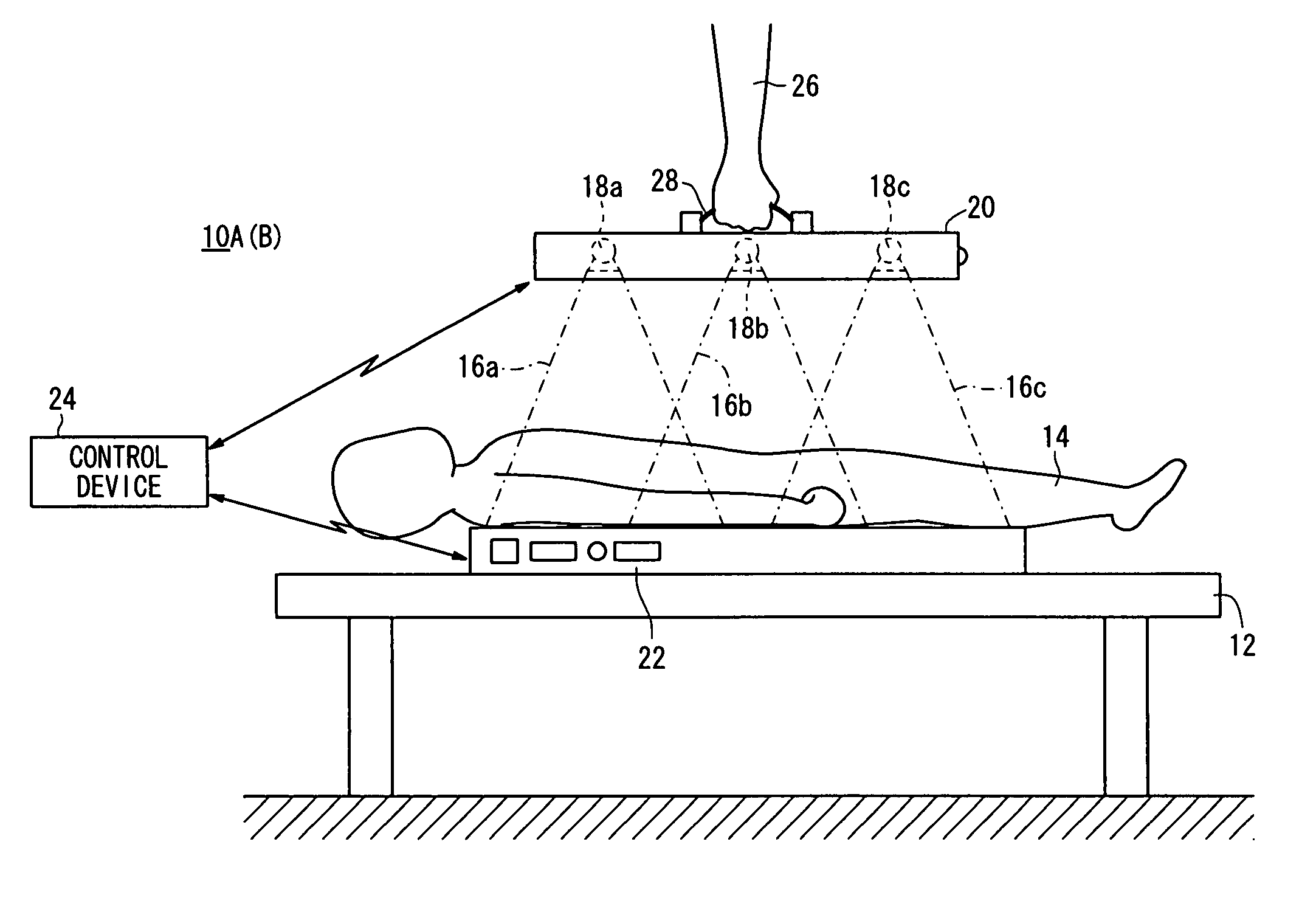
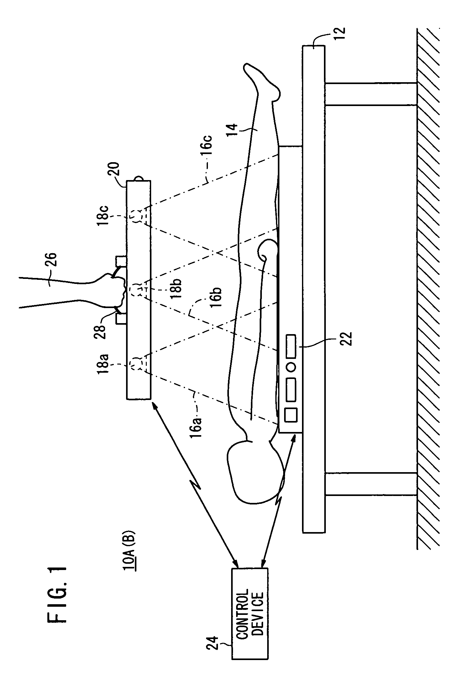
[0238]According to a first modification, as shown in FIGS. 15A and 15B, a radiation output device 20 houses two radiation sources 18a, 18b therein.

[0239]In this case, the radiation sources 18a, 18b apply radiation 16a, 16b respectively to the subject 14. During the second image capturing process, doses of radiation 16a, 16b are weighted based on the first radiographic image.

[0240]In this manner, in the case of the first modification, in which only two radiation sources 18a, 18b are housed in the radiation output device 20, by performing the aforementioned first image capturing process to acquire the first radiographic image, the same advantages as those of the first embodiment can be obtained.

[0241]As described above, according to the first embodiment and the first modification thereof, a first radiographic image is acquired, and doses of radiation emitted from two radiation sources 18a, 18b or three radiation sources 18a, 18b, 18c are weighted. However, the firs...

second modification

[Second Modification]

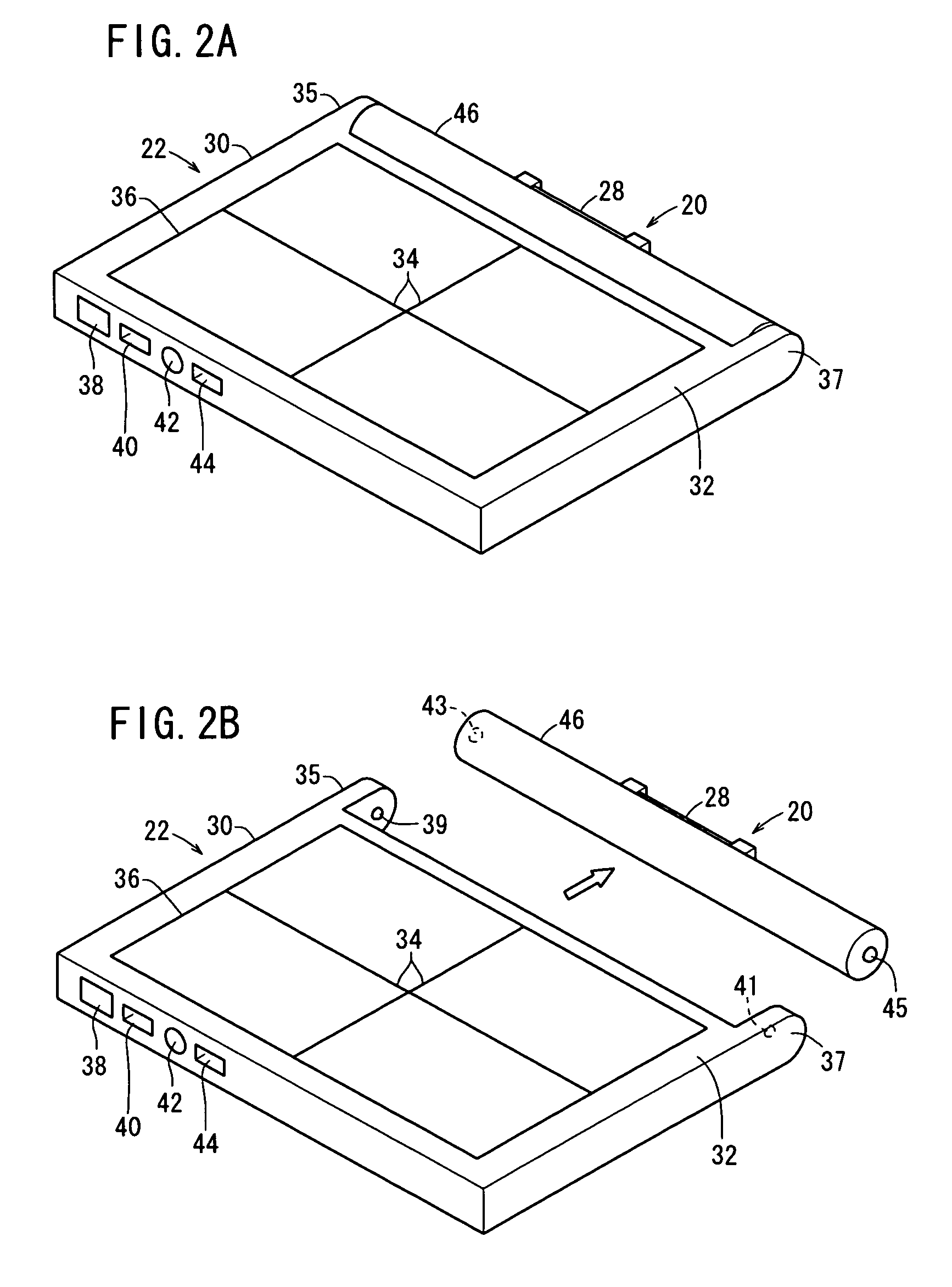
[0242]According to a second modification, as shown in FIGS. 16A and 16B, a casing 46 of the radiation output device 20 includes a recess 164 defined in a side thereof remote from the side at which radiation 16a through 16c is emitted from the radiation sources 18a through 18c. A collapsible grip 166 is pivotally movably disposed for storage in the recess 164. A touch sensor 52 is incorporated in the grip 166.

[0243]In the case that the doctor 26 is not carrying the radiation output device 20, the grip 166 is accommodated flatwise in the recess 164, as shown in FIG. 16A. If the doctor 26 turns the grip 166 about the pivoted end, then the grip 166 is raised out from the recess 164, so that the doctor 26 can grip the grip 166 (see FIG. 16B). The grip 166 and the touch sensor 52 offer the same advantages as those of the grip 28 and the touch sensor 52 according to the first embodiment. Further, in a case where the grip 166 is turned about the pivoted end back into th...

third modification

[Third Modification]

[0244]According to a third modification, as shown in FIGS. 17A and 17B, the casing 46 of the radiation output device 20 is of a rectangular shape, the planar area of which is substantially the same as the radiation detecting device 22. The casing 46 houses therein nine radiation sources 18a through 18i. The casing 46 is not required to house all nine of the radiation sources 18a through 18i, but may house at least three radiation sources.

[0245]The radiation sources 18a through 18i are arranged in a two-dimensional matrix facing toward the irradiated surface 32, which differs from the above-described linear array of radiation sources 18a through 18c that face toward the irradiated surface 32 (see FIGS. 1, 5A through 6B, 15A and 15B).

[0246]Further, the casing 46 has a grip 28 disposed on an upper surface thereof, and also has unlocking buttons 167 on opposite side surfaces thereof for releasing hooks 165, which are mounted on the bottom surface of the casing 46, fr...


PUM


Abstract

In a radiographic image-capturing system and radiographic image capturing method, a first image capturing process is performed, in which radiation is applied to a subject from at least one radiation source from among at least two radiation sources, whereby a first radiographic image is acquired. Based on the first radiographic image, respective doses of radiation to be emitted from the at least two radiation sources are weighted, and in accordance with such weighting, a second image capturing process is carried out, in which the respective radiation is applied to the subject from the at least two radiation sources.

Description

CROSS-REFERENCE TO RELATED APPLICATION[0001]This application is based upon and claims the benefit of priority from Japanese Patent Applications No. 2010-187303 filed on Aug. 24, 2010, No. 2010-187304 filed on Aug. 24, 2010, No. 2011-179096 filed on Aug. 18, 2011 and No. 2011-179097 filed on Aug. 18, 2011, of which the contents are incorporated herein by reference.BACKGROUND OF THE INVENTION[0002]1. Field of the Invention[0003]The present invention relates to a radiographic image capturing system and a radiographic image capturing method for applying radiation from a plurality of radiation sources housed in a radiation output device to a subject, detecting radiation that has passed through the subject with a radiation detecting device, and converting the detected radiation into radiographic images.[0004]2. Description of the Related Art[0005]In the medical field, there have widely been used radiographic image capturing systems, which apply radiation from a radiation source to a subje...

Claims


Application Information

Patent Timeline
Patent Type & Authority Patents(United States)
IPC IPC(8): H05G1/44
CPCA61B6/4283A61B6/527A61B6/4423A61B6/4007A61B6/488A61B6/465A61B6/4411A61B6/542
Inventor NISHINO, NAOYUKIOHTA, YASUNORI
Owner FUJIFILM CORP
Why Eureka
Try Eureka