Radiographic image capturing system and radiographic image capturing method
a radiographic image and imaging system technology, applied in medical science, diagnostics, electrical equipment, etc., can solve the problems of small radiation dose, difficult preparation of appropriate external power supply, field-emission radiation source may fail to capture radiation image, etc., to achieve effective radiographic image capture and easy enlarged radiation radiation range
- Summary
- Abstract
- Description
- Claims
- Application Information
AI Technical Summary
Benefits of technology
Problems solved by technology
Method used
Image
Examples
first modification
[First Modification]
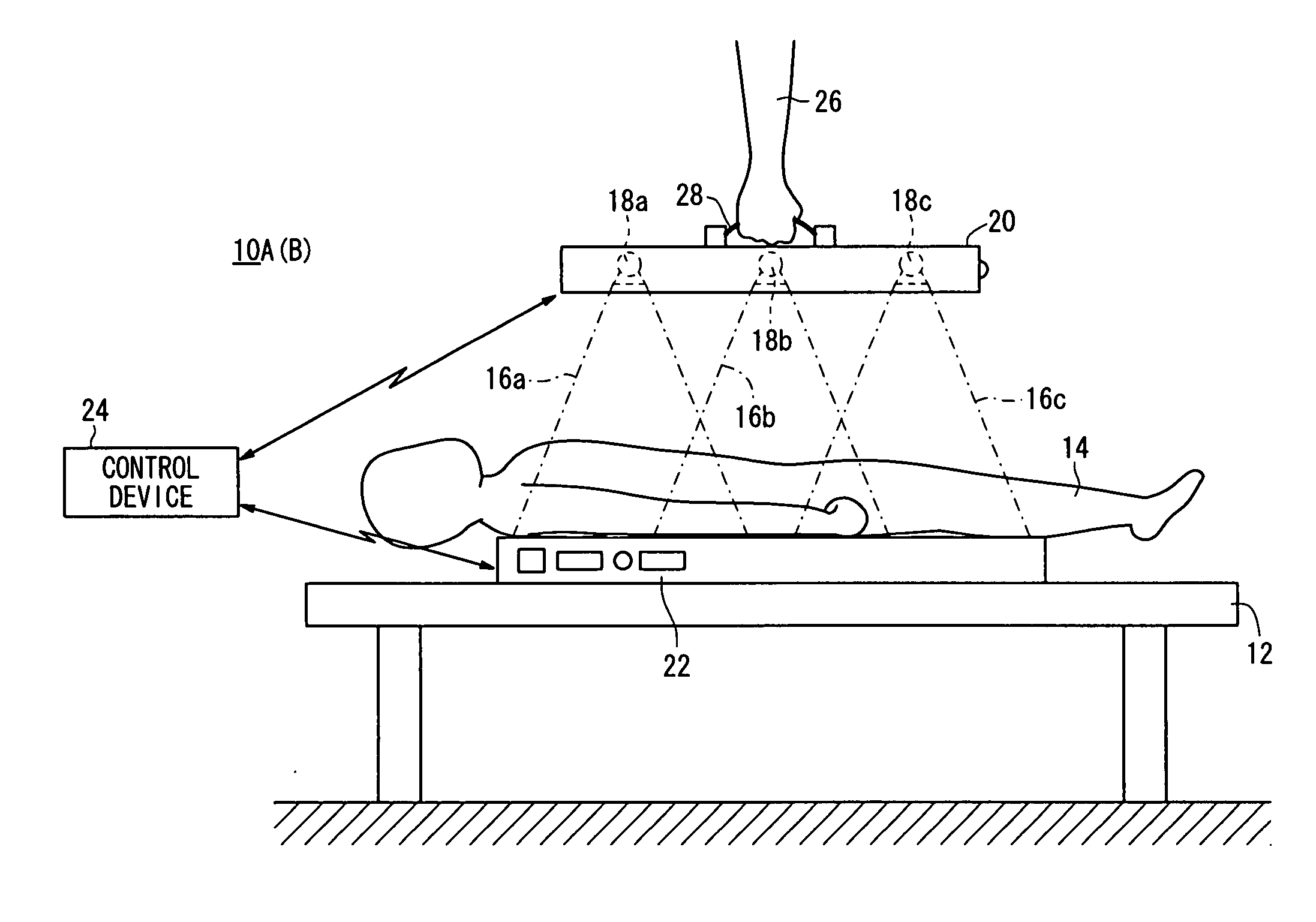
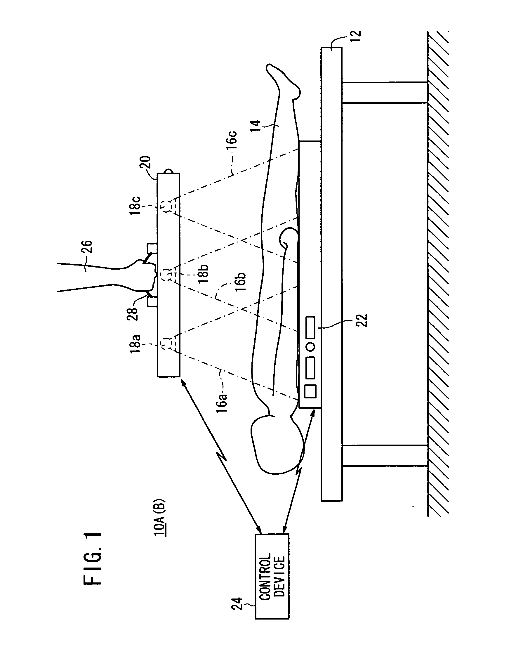
[0238]According to a first modification, as shown in FIGS. 15A and 15B, a radiation output device 20 houses two radiation sources 18a, 18b therein.
[0239]In this case, the radiation sources 18a, 18b apply radiation 16a, 16b respectively to the subject14. During the second image capturing process, doses of radiation 16a, 16b are weighted based on the first radiographic image.
[0240]In this manner, in the case of the first modification, in which only two radiation sources 18a, 18b are housed in the radiation output device 20, by performing the aforementioned first image capturing process to acquire the first radiographic image, the same advantages as those of the first embodiment can be obtained.
[0241]As described above, according to the first embodiment and the first modification thereof, a first radiographic image is acquired, and doses of radiation emitted from two radiation sources 18a, 18b or three radiation sources 18a, 18b, 18c are weighted. However, the first...
second modification
[Second Modification]
[0242]According to a second modification, as shown in FIGS. 16A and 16B, a casing 46 of the radiation output device 20 includes a recess 164 defined in a side thereof remote from the side at which radiation 16a through 16c is emitted from the radiation sources 18a through 18c. A collapsible grip 166 is pivotally movably disposed for storage in the recess 164. A touch sensor 52 is incorporated in the grip 166.
[0243]In the case that the doctor 26 is not carrying the radiation output device 20, the grip 166 is accommodated flatwise in the recess 164, as shown in FIG. 16A. If the doctor 26 turns the grip 166 about the pivoted end, then the grip 166 is raised out from the recess 164, so that the doctor 26 can grip the grip 166 (see FIG. 16B). The grip 166 and the touch sensor 52 offer the same advantages as those of the grip 28 and the touch sensor 52 according to the first embodiment. Further, in a case where the grip 166 is turned about the pivoted end back into th...
third modification
[Third Modification]
[0244]According to a third modification, as shown in FIGS. 17A and 17B, the casing 46 of the radiation output device 20 is of a rectangular shape, the planar area of which is substantially the same as the radiation detecting device 22. The casing 46 houses therein nine radiation sources 18a through 18i. The casing 46 is not required to house all nine of the radiation sources 18a through 18i, but may house at least three radiation sources.
[0245]The radiation sources 18a through 18i are arranged in a two-dimensional matrix facing toward the irradiated surface 32, which differs from the above-described linear array of radiation sources 18a through 18c that face toward the irradiated surface 32 (see FIGS. 1, 5A through 6B, 15A and 15B).
[0246]Further, the casing 46 has a grip 28 disposed on an upper surface thereof, and also has unlocking buttons 167 on opposite side surfaces thereof for releasing hooks 165, which are mounted on the bottom surface of the casing 46, fr...
PUM
 Abstract
Description
Claims
Application Information
 - R&D
- Intellectual Property
- Life Sciences
- Materials
- Tech Scout
- Unparalleled Data Quality
- Higher Quality Content
- 60% Fewer Hallucinations
Browse by: Latest US Patents, China's latest patents, Technical Efficacy Thesaurus, Application Domain, Technology Topic, Popular Technical Reports.
© 2025 PatSnap. All rights reserved.Legal|Privacy policy|Modern Slavery Act Transparency Statement|Sitemap|About US| Contact US: help@patsnap.com


