Collimator and optical filter device using the same

a filter device and collimator technology, applied in the field of collimators, can solve the problems of coupling loss, inability to obtain well-collimated light, so as to improve coupling efficiency, efficient incident effect, and efficient shape

Inactive Publication Date: 2008-03-04
NIPPON SHEET GLASS CO LTD
View PDF4 Cites 2 Cited by
  • Summary
  • Abstract
  • Description
  • Claims
  • Application Information

AI Technical Summary

Benefits of technology

[0015]Also, the collimator according to the invention is adapted so that the numerical aperture (NA) of the large diameteroptical fiber is equal to or larger than a numerical aperture (NA) of each of the optical fibers of the optical fiber bundle, and that an end face of the optical fiber bundle is in mechanical contact with one of the end faces of the large diameter optical fiber. Thus, light beams outputted from the optical fiber bundle are more efficiently incident upon the large diameter optical fiber. Consequently, coupling efficiency is improved. Also, the collimator according to the invention may be adapted so that the large diameter optical fiber may be wound by (½) turn or more at a predetermined radius of curvature. Thus, as compared with the case where the large diameter optical fiber is linearly shaped, the distribution of the intensity of light beams can efficiently be shaped at a shorter length. Consequently, the invention can obtain an advantage in that the light distribution at the incidence of light beams can be substantially compensated by using such a short large-diameter optical fiber.
[0016]The collimator of the invention can efficiently transmit light beams outputted from a plurality of optical fibers of a optical fiber bundle, and can obtain favorably collimated light beams. Thus, the invention can realize an optical filter device that is most suitable for an optical measuring apparatus adapted to deal an extremely minute amount of light. Also, the invention can realize a high-performance optical measuring apparatus.

Problems solved by technology

However, the transmission system using such an optical fiber bundle has a problem that in the case of using the related optical fiber collimator, well-collimated light beams cannot be obtained.
Consequently, well-collimated light cannot be obtained.
Therefore, in the case of constituting a system in which an optical filter is inserted between a pair of collimator lenses, coupling loss is caused by light beams traveling obliquely with respect to the optical axis of each of the collimator lenses.
Consequently, the optical coupling loss caused between a pair of collimator lenses is very large.
Especially, in a case where the optical filter is a bandpass filter, the system has a poor cutoff characteristic, because the designed characteristic of a dielectric multilayer filter is deviated from a necessary cutoff characteristic for the light beams traveling obliquely with respect to the optical axis of the collimator lens.

Method used


Image

  • Collimator and optical filter device using the same
  • Collimator and optical filter device using the same
  • Collimator and optical filter device using the same

Examples


example

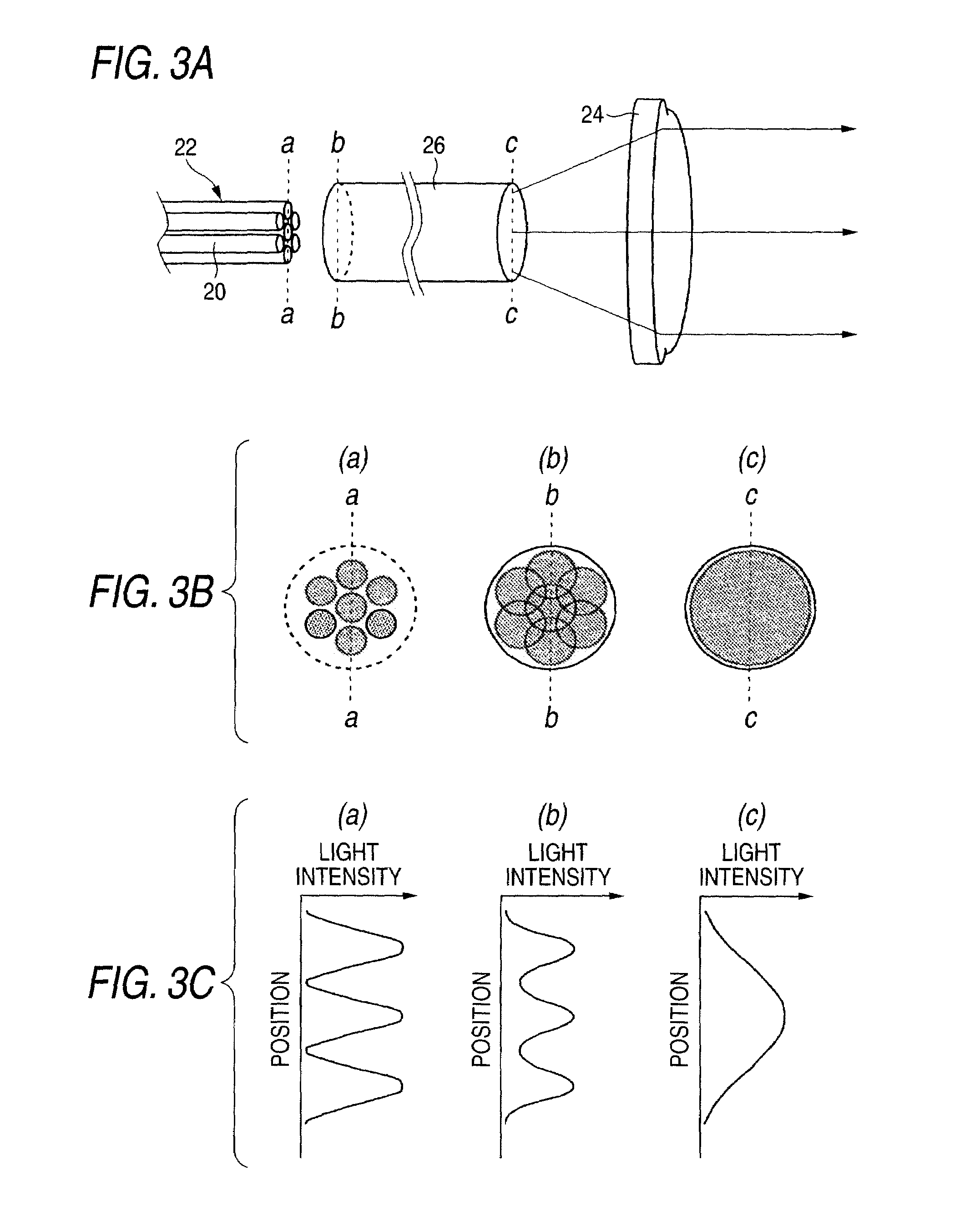
[0029]FIGS. 3A to 3C is an explanatory view illustrating an example of the collimator according to the invention. Further, FIG. 3Aschematically shows the configuration of this collimator. FIG. 3B schematically shows light distributions obtained at different positions. FIG. 3C shows the distribution of the intensity of light, which is obtained at each of the different positions.

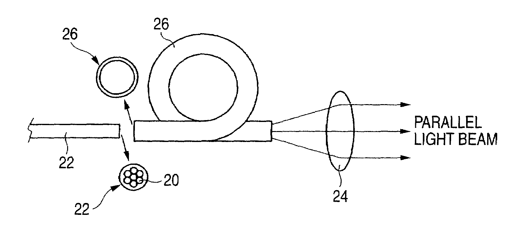
[0030]As shown in FIG. 3A, the optical fiber bundle 22 is configured as one optical transmission path by bundling a large number of the multimode optical fibers 20 (in this example, a total of 7 optical fibers, among which 6 optical fibers are disposed around the remaining 1 optical fiber at places symmetrical to one another to close to the central optical fiber) The incidence-side end faces of the optical fiber bundle 22 and the large diameter optical fiber 26 are placed close to each other so that effective coupling loss is minimized. Although the large diameter optical fiber 26 is drawn by omitting a middle...


PUM


Abstract

It is a collimator adapted to convert divergent light beams outputted from an optical fiber bundle to parallel light beams through a collimator lens. A large diameter optical fiber is disposed between an optical fiber bundle, which is a bundle of a large number of multimode optical fibers and serves as one optical transmission path, and a collimator lens. A cross-section of the core of the large diameter optical fiber is larger than a range in which the cores of the optical fibers of the optical fiber bundle are present. Also, a group of divergent light beams outputted from the optical fibers of the optical fiber bundle is converted by the large diameter optical fiber to one light beam.

Description

BACKGROUND OF THE INVENTION[0001]1. Field of the Invention[0002]The present invention relates to a collimator adapted to convert divergent light beams outputted from each of optical fibers of an optical fiber bundle to parallel light beams through a collimator lens. More particularly, the invention relates to a collimator having a structure in which a large diameter optical fiber is disposed between the collimator lens and an optical fiber bundle obtained by tying a large number of multimode optical fibers in a bundle serving as a single optical transmission path, and also relates to an optical filter device incorporating the collimator at an incident side thereof, and to an optical measuring apparatus incorporating the collimator at an incident side thereof.[0003]2. Related Art[0004]An optical fiber collimator is a device adapted to convert divergent light beams outputted from an optical fiber 10 to parallel light beams through a collimator lens 12, as shown in FIG. 6A. The optical...

Claims


Application Information

Patent Timeline
Patent Type & Authority Patents(United States)
IPC IPC(8): G02B6/32
CPCG02B6/2937G02B6/29389G02B6/32G02B6/4215G02B6/04
Inventor NAKAMA, KENICHIHIKICHI, NAOKO
Owner NIPPON SHEET GLASS CO LTD
Why Eureka
Try Eureka