Retinal scanning display with exit pupil expanded by optics offset from intermediate image plane

a technology of optical offset and display image, applied in the field of retina scanning display device, can solve the problems of inability to desirably focus a display image onto the viewer's retina, viewer may possibly lose alignment with the exit pupil, etc., and achieve the effect of reducing or eliminating the degradation of the quality of the displayed imag

Inactive Publication Date: 2009-11-05
BROTHER KOGYO KK
View PDF6 Cites 3 Cited by
  • Summary
  • Abstract
  • Description
  • Claims
  • Application Information

AI Technical Summary

Benefits of technology

[0016]For a diffraction grating having periodically repeated light-transmissive or light-reflective portions, there are enhanced both constructive interference of wavelets emanating from source points on those repeated portions of the diffraction grating, and diffraction efficiency of the diffraction grating for incident light thereon at an increasing level with an increase in number of concurrently-illuminated ones of those repeated portions with the incident light.
[0018]Therefore, it is important to adequately optimize a dimensional relationship between the grating pitch and the incident-beam diameter, for achieving high efficiency with which the incident beam is diffracted at the diffraction grating.
[0021]Concurrently-illuminated ones of the repeated light-transmissive or light-reflective portions of the diffraction grating with a incident beam thereon reduces in number with a reduction in diameter of the incident beam.
[0023]In other words, the aforementioned conventional technique, when implemented without any modifications, increases a tendency that the incident beam passes through the diffraction grating with scattering, resulting in an increased percentage of the incident beam which is lost without being converted into diffracted light.
[0028]Further, this conventional technique, when implemented with dust deposited on the surface of the diffraction grating, or with defects introduced during fabrication of the diffraction grating, easily allows those dust and defects to make noises that could adversely affect diffracted light.
[0031]Under the circumstances described above, there is a need of expanding an exit pupil of a retinal scanning display device, while reducing or eliminating degradation in quality of a displayed image.GENERAL OVERVIEW OF THE INVENTION

Problems solved by technology

For this reason, when the exit pupil of the retinal scanning display device is smaller in size than the viewer's eye pupil, a viewer may possibly lose alignment with the exit pupil.
In other words, if the exit pupil of a retinal scanning display device is smaller than a viewer's eye pupil, light exiting the retinal scanning display device may possibly fail to enter the viewer's eye pupil adequately, resulting in an incapability of desirably focusing a display image onto the viewer's retina.

Method used


Image

  • Retinal scanning display with exit pupil expanded by optics offset from intermediate image plane
  • Retinal scanning display with exit pupil expanded by optics offset from intermediate image plane
  • Retinal scanning display with exit pupil expanded by optics offset from intermediate image plane

Examples


first embodiment

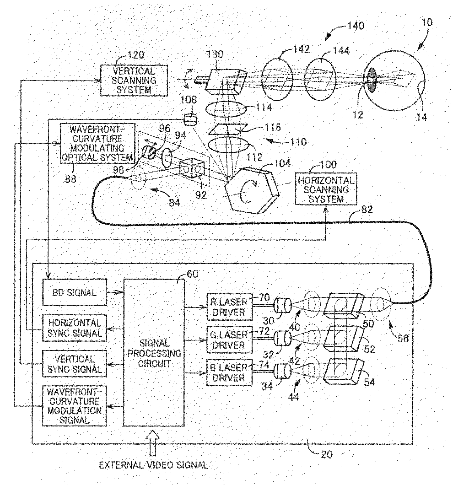
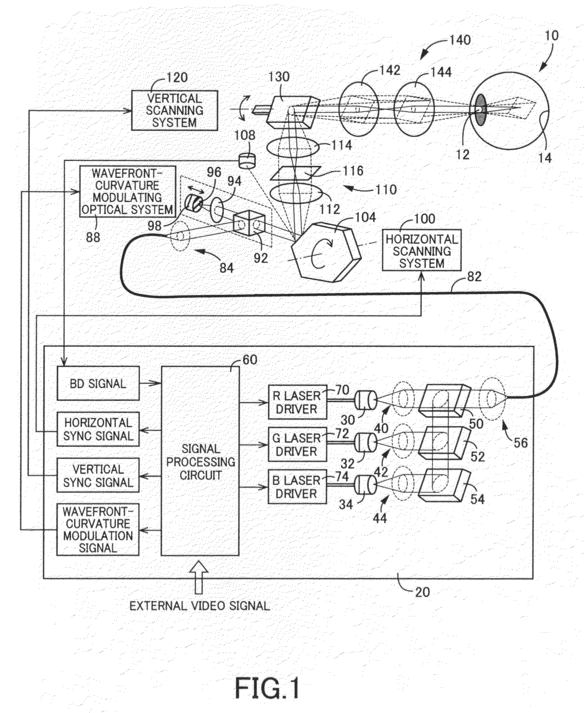
[0292]Referring now to FIG. 1, there is schematically illustrated a retinal scanning display device (hereinafter, abbreviated to “RSD”) constructed according to a first illustrative embodiment of the present invention. This RSD is designed to project a laser beam as a light beam directly onto a retina 14 through an eye pupil 12 of a viewer's eye 10 and scan the projected light beam on the retina 14, to thereby display an image.

[0293]Throughout the description, the expression “project a laser beam directly onto the retina 14” means not only an arrangement in which light exiting the RSD enters the eye pupil 12 without passing through any separate optics, but also an arrangement in which light exiting the RSD enters the eye pupil 12 through separate optics (e.g., a mirror, a lens, etc.) for causing an optical action (e.g., reflection, refraction, etc.) without visualization by physical display screen.

[0294]As illustrated in FIG. 1, the RSD includes a light source unit 20. The light sou...

second embodiment

[0354]Next, a second illustrative embodiment of the present invention will be described below.

[0355]The present embodiment is different from the first embodiment only with respect to the configuration of the diffractive device, and is common to the first embodiment with respect to the remaining elements.

[0356]Therefore, only the different elements of the present embodiment from those of the first embodiment will be described below in greater detail, while the common elements of the present embodiment to those of the first embodiment will be omitted in the description using the identical reference numerals or names for reference.

[0357]In the first embodiment, the diffractive device 116 is configured such that incident light thereon is diffracted only in one dimension. In contrast, in the present embodiment, as illustrated in FIG. 11, a diffractive device or element 190 is formed principally with a two-dimensional diffraction grating 192 operable to diffract incident light thereon in ...

third embodiment

[0360]Next, a third illustrative embodiment of the present invention will be described below.

[0361]The present embodiment is different from the second embodiment only with respect to the configuration of the diffractive device, and is common to the second embodiment with respect to the remaining elements.

[0362]Therefore, only the different elements of the present embodiment from those of the second embodiment will be described below in greater detail, while the common elements of the present embodiment to those of the second embodiment will be omitted in the description using the identical reference numerals or names for reference.

[0363]In the second embodiment, incident light on the one two-dimensional diffraction grating 192 is diffracted in two dimensions. On the other hand, in the present embodiment, as illustrated in FIG. 12, a diffractive device 210 is configured to include two one-dimensional diffraction gratings 212 and 214 at each of which incident light thereon is diffract...


PUM


Abstract

A retinal scanning display device is disclosed which is configured to include: a light source emitting a light beam; a scanner scanning onto a viewer's retina the light beam emitted from the light source; a light exit at which the light beam scanned by the scanner exits the retinal scanning display device; and a pupil expanding element operable to expand an exit pupil of the retinal scanning display device. The pupil expanding element may be disposed at a position which is offset from an intermediate image plane occurring between the light source and the light exit, along and within an optical path defined between the light source and the light exit.

Description

CROSS-REFERENCE TO RELATED APPLICATIONS[0001]This application is based on Japanese Patent Applications No. 2004-282932 filed Sep. 29, 2004, No. 2005-065130 filed Mar. 9, 2005 and No. 2005-065132 filed Mar. 9, 2005, and International Application No. PCT / JP2005 / 017680 filed Sep. 27, 2005, the contents of which are incorporated hereinto by reference.[0002]This application is a continuation of U.S. patent application Ser. No. 11 / 727,854 filed Mar. 28, 2007, which is a continuation-in-part application of International Application No. PCT / JP2005 / 017680 filed Sep. 27, 2005, now pending, which was published in Japanese under PCT Article 21(2).BACKGROUND OF THE INVENTION[0003]1. Field of the Invention[0004]The invention relates to retinal scanning display devices configured to allow a light beam to be projected directly onto a retina of a viewer, and allow the projected light beam to be scanned onto the retina, to thereby display an image onto the retina. The invention relates more particula...

Claims


Application Information

Patent Timeline
Patent Type & Authority Applications(United States)
IPC IPC(8): G02B26/10
CPCG02B26/06G02B27/0081G02B26/125G02B26/101
Inventor WATANABE, MITSUYOSHI
Owner BROTHER KOGYO KK
Why Eureka
Try Eureka